4-12. Setting Internal DIP Switches
.When DIP switch positions are changed, the
unit must be turned Off and then On again in order for the new settings to be active. DIP switches are only read on power up.
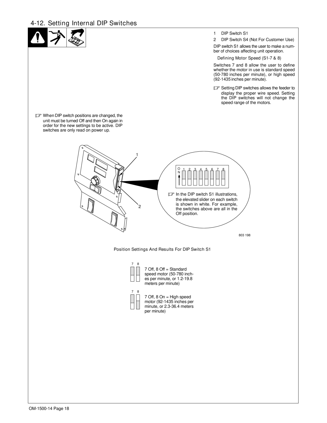
1
2
1DIP Switch S1
2DIP Switch S4 (Not For Customer Use)
DIP switch S1 allows the user to make a num- ber of choices affecting unit operation.
wDefining Motor Speed (S1-7 & 8)
Switches 7 and 8 allow the user to define whether the motor in use is standard speed
.Setting DIP switches allows the feeder to
display the proper wire speed. Setting the DIP switches will not change the speed range of the motors.
ON 1 2 3 4 5 6 7 8
.In the DIP switch S1 illustrations,
the elevated slider on each switch is shown in white. For example, the switches above are all in the Off position.
803 198
Position Settings And Results For DIP Switch S1
7 8
7 Off, 8 Off = Standard speed motor
7 8
7 Off, 8 On = High speed motor
