4-11. Installing And Threading Welding Wire
Tools Needed:
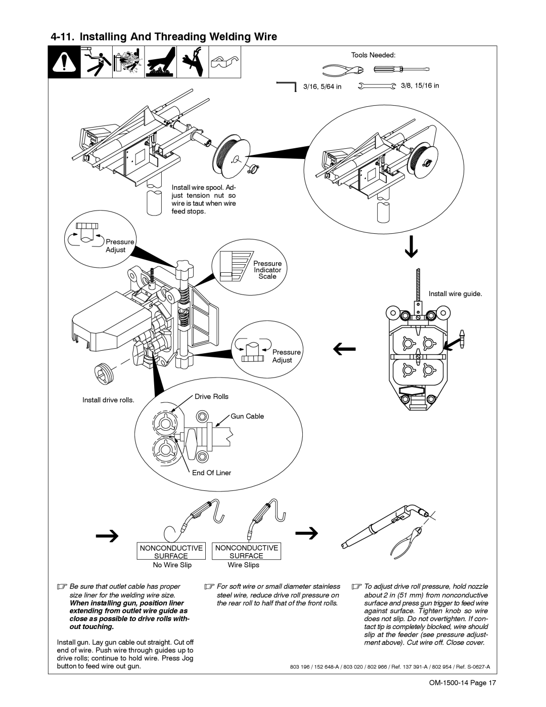
3/16, 5/64 in | 3/8, 15/16 in |
Pressure
Adjust
Install drive rolls.
Install wire spool. Ad- just tension nut so wire is taut when wire feed stops.
Pressure
Indicator
Scale
Install wire guide.
![]() Pressure
Pressure
Adjust
![]() Drive Rolls
Drive Rolls
![]() Gun Cable
Gun Cable
End Of Liner
| NONCONDUCTIVE |
| NONCONDUCTIVE |
|
| SURFACE |
| SURFACE |
|
| No Wire Slip |
| Wire Slips |
|
. Be sure that outlet cable has proper | . For soft wire or small diameter stainless | . To adjust drive roll pressure, hold nozzle | ||
size liner for the welding wire size. |
| steel wire, reduce drive roll pressure on | about 2 in (51 mm) from nonconductive | |
When installing gun, position liner |
| the rear roll to half that of the front rolls. | surface and press gun trigger to feed wire | |
extending from outlet wire guide as |
|
| against surface. Tighten knob so wire | |
close as possible to drive rolls with- |
|
| does not slip. Do not overtighten. If con- | |
out touching. |
|
| tact tip is completely blocked, wire should | |
Install gun. Lay gun cable out straight. Cut off |
|
| slip at the feeder (see pressure adjust- | |
|
| ment above). Cut wire off. Close cover. | ||
end of wire. Push wire through guides up to |
|
|
| |
drive rolls; continue to hold wire. Press Jog |
|
|
| |
button to feed wire out gun. |
| 803 196 / 152 | ||