DS-74DX Swingarc
DS-74DX12, and DS-74DX16
OM-1500-14 207 499H
Processes
From Miller to You
TABLE OF CONTENTS
SECTION 6 − SETTING SEQUENCE PARAMETERS
TABLE OF CONTENTS
OPTIONS AND ACCESSORIES WARRANTY
SECTION 1 − SAFETY PRECAUTIONS - READ BEFORE USING
1-1. Symbol Usage
1-2. Arc Welding Hazards
ELECTRIC SHOCK can kill
FUMES AND GASES can be hazardous
ARC RAYS can burn eyes and skin
WELDING can cause fire or explosion
FLYING METAL or DIRT can injure eyes
1-3. Additional Symbols For Installation, Operation, And Maintenance
WELDING WIRE can cause injury
FIRE OR EXPLOSION hazard
FALLING UNIT can cause injury
1-5. Principal Safety Standards
1-4. California Proposition 65 Warnings
1-6. EMF Information
For Gasoline Engines
2-1. Symboles utilisés
2-2. Dangers relatifs au soudage à l’arc
SECTION 2 − CONSIGNES DE SÉCURITÉ − LIRE AVANT UTILISATION
UNE DÉCHARGE ÉLECTRIQUE peut entraîner la mort
LES FUMÉES ET LES GAZ peuvent être dangereux
DES PIÈCES CHAUDES peuvent provoquer des brûlures graves
LE SOUDAGE peut provoquer un in cendie ou une explosion
LES CHAMPS MAGNETIQUES peuv- ent affecter des implants médicaux
LE BRUIT peut endommager l’ouïe
LES BOUTEILLES peuvent exploser si elles sont endommagées
Risque D’INCENDIE OU D’EXPLO- SION
2-4. Proposition californienne 65 Avertissements
LES FILS DE SOUDAGE peuvent provoquer des blessures
DES ORGANES MOBILES peuvent provoquer des blessures
LIRE LES INSTRUCTIONS
2-6. Information EMF
2-5. Principales normes de sécurité
En ce qui concerne les implants médicaux
OM-1500-14 Page
SECTION 4 − INSTALLATION
3-1. Specifications
4-1. Installing Swivel Into Pipe Post
SECTION 3 − INTRODUCTION
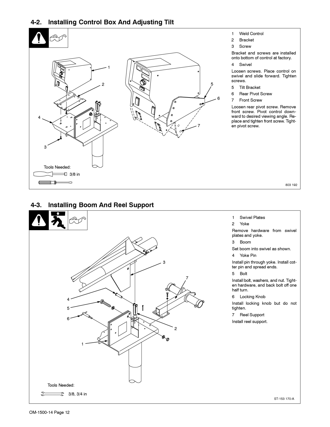
4-2. Installing Control Box And Adjusting Tilt
4-3. Installing Boom And Reel Support
swivel and slide forward. Tighten
Loosen rear pivot screw. Remove
Tighten bolt to secure liner in wire
4-4. Installing Wire Guide Extension
guide fitting. Do not overtighten bolt
Shielding gas pressure not to
4-5. Equipment Connection Diagram
exceed 100 PSI 689 kPa
4-7. 14-Pin Plug Information
4-6. Control Box Connections
Pin Information
4-8. Removing Safety Collar And Adjusting Boom
4-10. Wire Type, Size, And Feed Speed Capability Table
4-9. Gun Recommendation Table
Wire Type
4-11. Installing And Threading Welding Wire
When installing gun, position liner
extending from outlet wire guide as
close as possible to drive rolls with
Position Settings And Results For DIP Switch S1
4-12. Setting Internal DIP Switches
w Defining Motor Speed S1-7
4-13. Power Source Selection Menu
Power Source
Disabling The Power Source Selection Menu
Non-CE Model Shown
5-2. Power Switch
5-3. Left/Right Select Switch
SECTION 5 − OPERATION
5-1. Operational Terms
5-4. Jog/Purge Switch
5-5. Front Panel Controls
Wire Speed
Adjust
5-6. Program Push Button
5-7. Upper Display
Program
Volts
5-9. Setup Push Button
5-8. Lower Display
Wire Speed
Setup
5-10. Adjust Control
5-11. Sequence Push Button
Adjust
Start
5-12. Auxiliary Menus
5-12 Auxiliary Menus Continued
Reset To Factory Settings
Power Source Selection Menu
Trigger Hold Setup
Wire Feed Speed Units
5-12 Auxiliary Menus Continued
Burnback
6-1. Sequence Parameters In A Program
SECTION 6 − SETTING SEQUENCE PARAMETERS
Sequence
SECTION 7 − SETTING DUAL SCHEDULE PARAMETERS
7-1. Optional Dual Schedule Switch Diagrams
COM1
TRG1
TCH1
COM2
SECTION 8 − MAINTENANCE & TROUBLESHOOTING
7-3. Diagnostics For User Defined Options
8-1. Routine Maintenance
ERR OPT1
8-2. Troubleshooting
Disconnect power before troubleshooting
Trouble
Remedy
SECTION 9 − ELECTRICAL DIAGRAM
Figure 9-1. Circuit Diagram
OM-1500-14 Page
204 144-C
SECTION 10 − PARTS LIST
Figure 10-1. Main Assembly
Circuit Card Assy,Switches
Housing Plug+Pins, service kit
Housing Plug+Skts, service kit
Figure 10-2. Control Box
Harness Connectors/Receptacles
Figure 10-2. Control Box Continued
Hardware is common and not available unless listed
Figure 10-3. Boom Assembly
ST-142 306-H
Figure 10-3. Boom Assembly Figure 10-1 Item
Figure 10-4. Drive Assembly, Wire Figure 10-1 Items 26 and
Figure 10-4. Drive Assembly, Wire
802 977-B
Figure 10-4. Drive Assembly, Wire continued
Figure 10-5. Support, Hub and Reel Figure 10-1 Item
Figure 10-5. Support, Hub & Reel
Ring, Retaining Spool
Table 10-1. Drive Roll and Wire Guide Kits
Wire Size
V-GROOVE
U-GROOVE
Page
Over 80,000 trained since
Start Your Professional Welding Career Now
400 Trade Square East, Troy, Ohio
Page
Warranty Questions?
Service
Call 1-800-4-A-MILLER for your local Miller distributor
Support
For Service
Contact a DISTRIBUTOR or SERVICE AGENCY near you
Owner’s Record
Please complete and retain with your personal records