Diagnostics | |
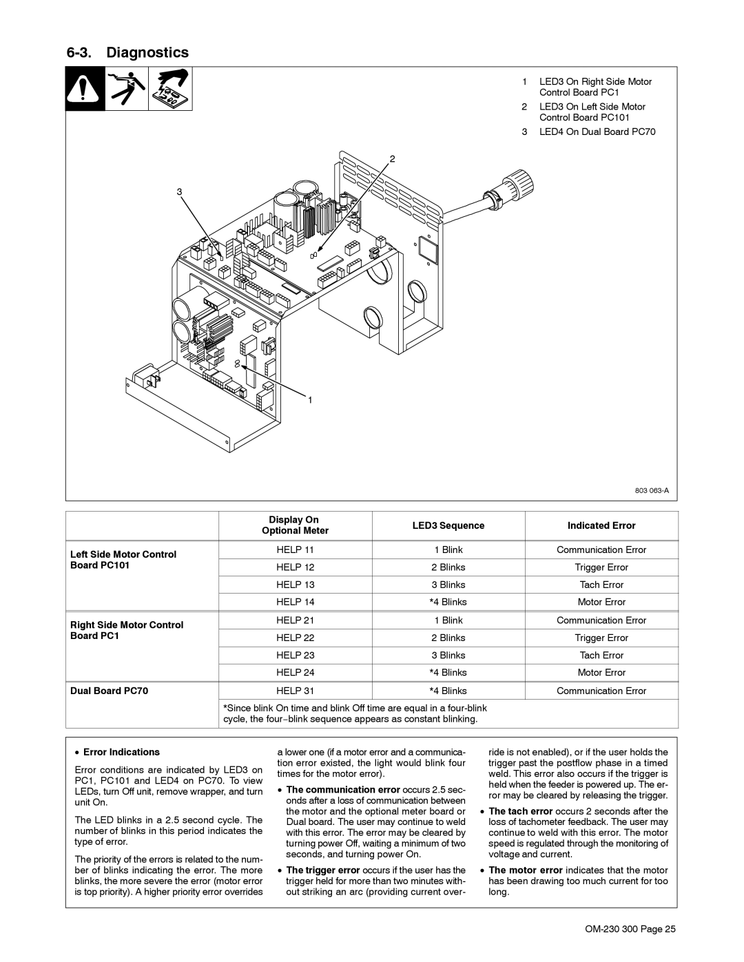
| 1 LED3 On Right Side Motor |
| Control Board PC1 |
| 2 LED3 On Left Side Motor |
| Control Board PC101 |
| 3 LED4 On Dual Board PC70 |
| 2 |
| 3 |
| 1 |
| 803 |
|
| Display On |
| LED3 Sequence |
| Indicated Error | ||
| Optional Meter |
|
| |||||
|
|
|
|
|
| |||
|
|
|
|
|
|
|
| |
|
|
|
|
|
|
|
| |
Left Side Motor Control |
| HELP 11 |
| 1 Blink |
|
| Communication Error | |
|
|
|
|
|
|
| ||
Board PC101 |
| HELP 12 |
| 2 Blinks |
|
| Trigger Error | |
|
|
|
|
|
|
|
| |
|
| HELP 13 |
| 3 Blinks |
|
| Tach Error | |
|
|
|
|
|
|
|
| |
|
| HELP 14 |
| *4 Blinks |
|
| Motor Error | |
|
|
|
|
|
|
|
| |
|
|
|
|
|
|
|
| |
Right Side Motor Control |
| HELP 21 |
| 1 Blink |
|
| Communication Error | |
|
|
|
|
|
|
| ||
Board PC1 |
| HELP 22 |
| 2 Blinks |
|
| Trigger Error | |
|
|
|
|
|
|
|
| |
|
| HELP 23 |
| 3 Blinks |
|
| Tach Error | |
|
|
|
|
|
|
|
| |
|
| HELP 24 |
| *4 Blinks |
|
| Motor Error | |
|
|
|
|
|
|
|
| |
|
|
|
|
|
|
|
| |
Dual Board PC70 |
| HELP 31 |
| *4 Blinks |
|
| Communication Error | |
|
|
|
|
| ||||
| *Since blink On time and blink Off time are equal in a |
|
| |||||
| cycle, the four−blink sequence appears as constant blinking. |
|
|
| ||||
|
|
|
|
|
|
| ||
|
|
|
| |||||
• Error Indications | a lower one (if a motor error and a communica- |
| ride is not enabled), or if the user holds the | |||||
Error conditions are indicated by LED3 on | tion error existed, the light would blink four |
| trigger past the postflow phase in a timed | |||||
times for the motor error). |
|
| weld. This error also occurs if the trigger is | |||||
PC1, PC101 and LED4 on PC70. To view |
|
| ||||||
• The communication error occurs 2.5 sec- |
| held when the feeder is powered up. The er- | ||||||
LEDs, turn Off unit, remove wrapper, and turn |
| |||||||
| ror may be cleared by releasing the trigger. | |||||||
unit On. | onds after a loss of communication between |
| ||||||
• The tach error occurs 2 seconds after the | ||||||||
The LED blinks in a 2.5 second cycle. The | the motor and the optional meter board or | |||||||
Dual board. The user may continue to weld |
| loss of tachometer feedback. The user may | ||||||
number of blinks in this period indicates the | with this error. The error may be cleared by |
| continue to weld with this error. The motor | |||||
type of error. | turning power Off, waiting a minimum of two |
| speed is regulated through the monitoring of | |||||
The priority of the errors is related to the num- | seconds, and turning power On. |
| voltage and current. | |||||
• The trigger error occurs if the user has the | • The motor error indicates that the motor | |||||||
ber of blinks indicating the error. The more | ||||||||
blinks, the more severe the error (motor error | trigger held for more than two minutes with- |
| has been drawing too much current for too | |||||
is top priority). A higher priority error overrides | out striking an arc (providing current over- |
| long. | |||||
|
|
|
|
|
|
|
| |