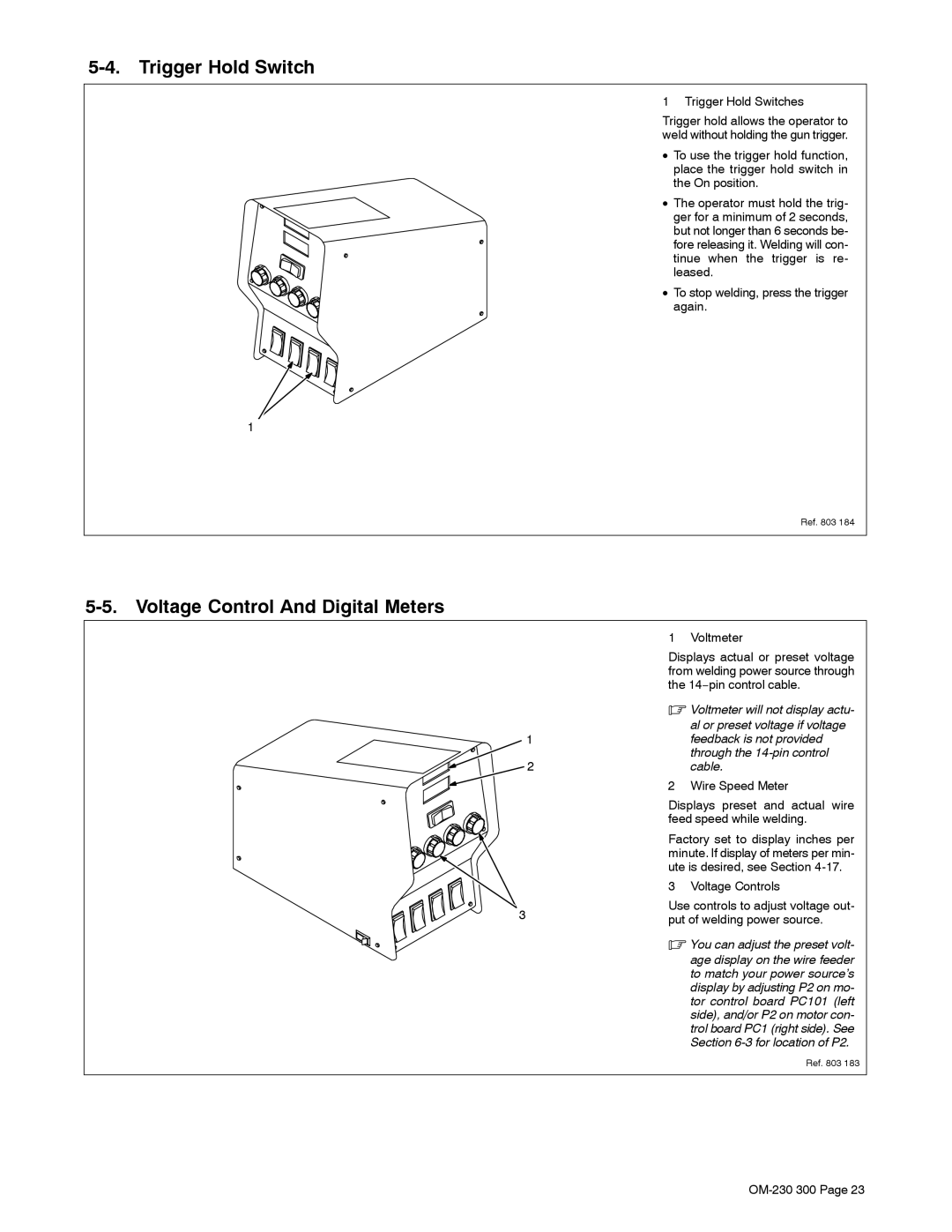
5-4. Trigger Hold Switch
1 Trigger Hold Switches
Trigger hold allows the operator to weld without holding the gun trigger.
• To use the trigger hold function, place the trigger hold switch in the On position.
• The operator must hold the trig- ger for a minimum of 2 seconds, but not longer than 6 seconds be- fore releasing it. Welding will con- tinue when the trigger is re- leased.
• To stop welding, press the trigger again.
1
Ref. 803 184
5-5. Voltage Control And Digital Meters
1 Voltmeter
1
2
3
Displays actual or preset voltage from welding power source through the 14−pin control cable.
.Voltmeter will not display actu-
al or preset voltage if voltage feedback is not provided through the
2 Wire Speed Meter
Displays preset and actual wire feed speed while welding.
Factory set to display inches per minute. If display of meters per min- ute is desired, see Section
3 Voltage Controls
Use controls to adjust voltage out- put of welding power source.
.You can adjust the preset volt-
age display on the wire feeder to match your power source’s display by adjusting P2 on mo- tor control board PC101 (left side), and/or P2 on motor con- trol board PC1 (right side). See Section
Ref. 803 183