Item | Diagram | Part | Description |
|
No. | marking | No. | Quantity | |
|
|
| Figure |
|
|
|
|
|
|
. . 54 . . . . | . . . . . . . . . | ♦028 770 . . | Potentiometer, Cp Std Slot 1t 2w 1m | . . . 1 |
. . 55 . . . . | . . . . . . . . . | . 073 562 . . | Potentiometer, Cp Std Slot 1t 2w 10k | . . . 1 |
. . 56 . . . . | . . . . . . . . . | . 134 201 . . | . . . 4 | |
. . 57 . . . | REED . . . | . 140 786 . . | Switch, Reed | . . . 1 |
. . 58 . . . . | . . . . . . . . . | . 169 089 . . | Door, Side Rh | . . . 1 |
. . 59 . . . . | . . . . . . . . . | . 605 970 . . | Washer, Shldr.252 Id 0.310 Odx.064t .500 Odx.250h Nyl | . . . 2 |
. . 60 . . . . | . . . . . . . . . | . . 211 989 . . | Fitting, W/Screen | . . . 1 |
+When ordering a component originally displaying a precautionary label, the label should also be ordered. ♦Part of 114 144 Spot Weld Control Option
♦♦Part of 144 931 Voltage Control Option
♦♦♦Part of 130 838 Water Flow Shutdown Switch Option
♦♦♦♦Part of 209 867 Voltage Sensing Lead Kit *Recommended Spare Parts.
To maintain the factory original performance of your equipment, use only Manufacturer’s Suggested Replacement Parts. Model and serial number required when ordering parts from your local distributor.
|
|
|
| . Hardware is common and |
| 4 | 10 |
| not available unless listed. |
*1 |
|
|
| |
9 |
| 11 |
| |
|
|
| ||
| 8 |
| 12 |
|
|
|
|
| |
| 7 |
| 13 |
|
|
|
|
| |
| 6 |
| 14 |
|
3 | 5 |
|
|
|
2 | 4 |
| 15 | 16 |
|
|
| ||
|
|
|
|
17
| 18 | 19 | 21 |
| 20 | ||
|
| ||
|
| 22 | |
|
|
| |
|
|
| 23 |
|
|
| 25 |
24 |
|
| 26 |
| 17 |
| |
|
|
| |
|
|
| 27 |
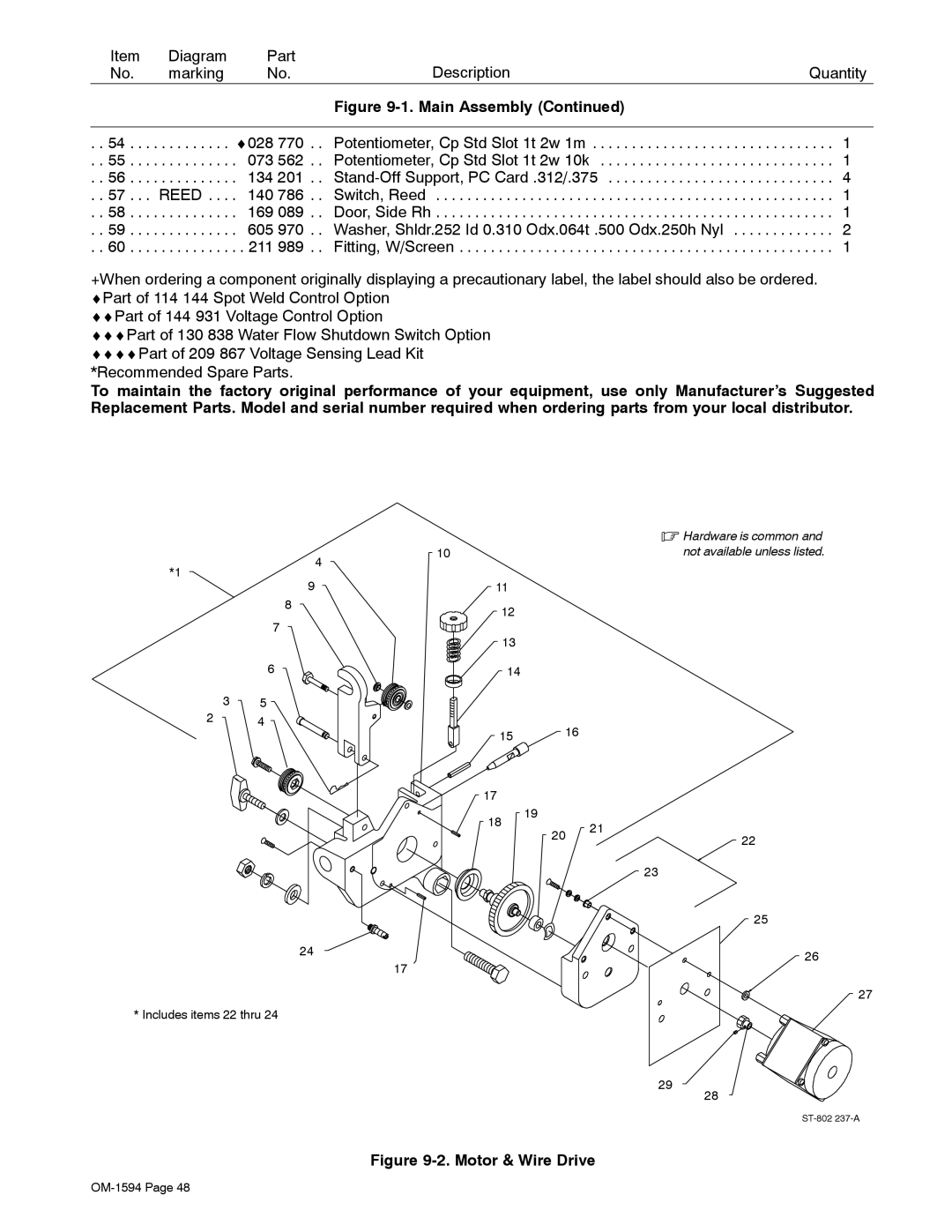
* Includes items 22 thru 24 |
|
|
|
|
|
| 29 |
|
|
| 28 |
|
|
|