5-15. Setting Switches For Preflow And Postflow
1
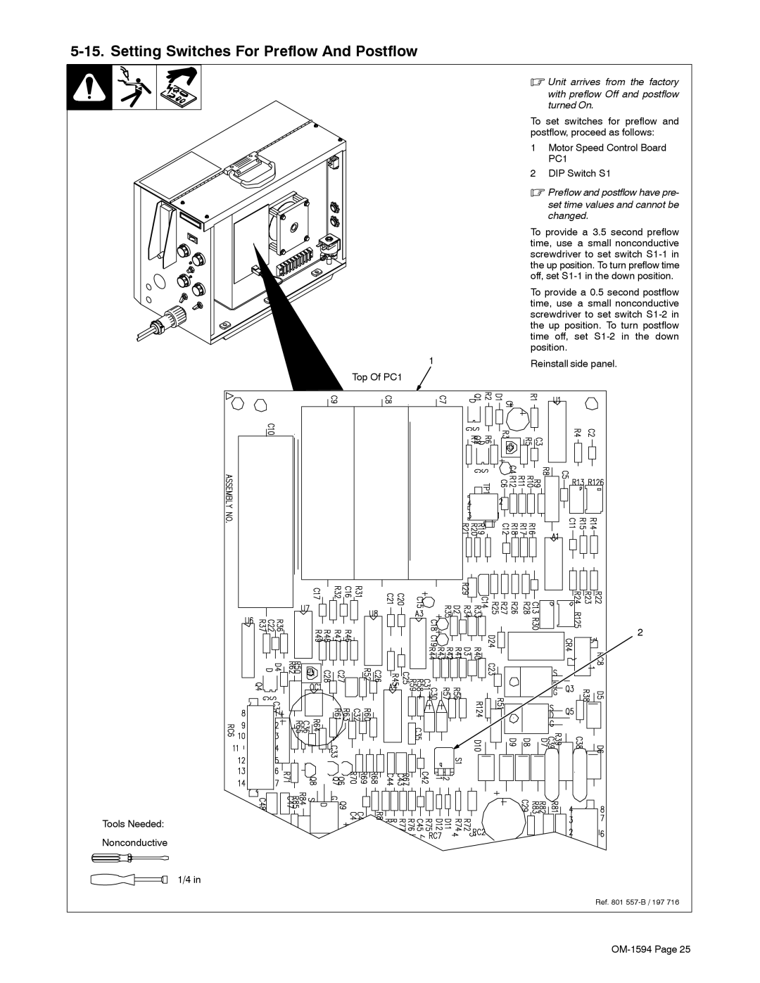
Top Of PC1
.Unit arrives from the factory
with preflow Off and postflow turned On.
To set switches for preflow and postflow, proceed as follows:
1Motor Speed Control Board PC1
2DIP Switch S1
.Preflow and postflow have pre-
set time values and cannot be changed.
To provide a 3.5 second preflow time, use a small nonconductive screwdriver to set switch
To provide a 0.5 second postflow time, use a small nonconductive screwdriver to set switch
Reinstall side panel.
2
Tools Needed:
Nonconductive
1/4 in
Ref. 801