Back Panel Input/Output for
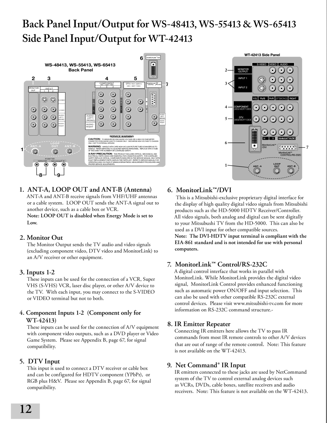
WS-48413, WS-55413, WS-65413
Back Panel
6MONITORLINKTM/DVI
2
MONITOR
OUT
3
I N P U T
12
V I D EO
AUDIO- LEFT / (MONO)
AUDIO -
RIGHT
Y
Pb
P r
AUDIO - L E FT /
AUDIO - RIGHT
4
COMPONENT 480 i / 480P/ 1080i
12
Y
G
Pb
B
P r
R
5
DTV(YPbPr/ GBRHV ) 480i / 480P /1080 i
MONITORLINKTM7 CONTROL
H
V
AUDIO-
LEFT/
(MONO)
AUDIO-
RIGHT
| AN T - A | LOO P | AN T - B |
1 | OUT | ||
|
|
| |
| IR EMITTER |
| |
| REPEATER | NetCommand IR |
|
SERVICE WARNING
CAUTION: TO MEASURE SECOND ANODE VOLTAGE USE A HIGH VOLTAGE METER CONNECTED FROM ANODE LEAD TO CHASSIS ONLY. DISCHARGE HIGH VOLTAGE TO CHASSIS ONLY, NOT TO EXTERNAL GROUND.
WARNING: HANDLE WITH CARE HIGH VACUUM PICTURE TUBE IS DANGEROUS TO HANDLE. REFER SERVICING TO QUALIFIED SERVICE PERSONNEL. REPLACE WITH A TUBE OF THE SAME TYPE NUMBER FOR CONTINUED SAFETY.
![]() 8
8![]()
![]() 9
9![]()
1. ANT-A, LOOP OUT and ANT-B (Antenna)
Note: LOOP OUT is disabled when Energy Mode is set to Low.
2. Monitor Out
The Monitor Output sends the TV audio and video signals (excluding component video, DTV video and MonitorLink) to an A/V receiver or other equipment.
3. Inputs 1-2
These inputs can be used for the connection of a VCR, Super VHS
4. Component Inputs 1-2 (Component only for WT-42413)
These inputs can be used for the connection of A/V equipment with component video outputs, such as a DVD player or Video Game System. Please see Appendix B, page 67, for signal compatibility.
5. DTV Input
This input is used to connect a DTV receiver or cable box and can be configured for HDTV component (YPbPr), or RGB plus H&V. Please see Appendix B, page 67, for signal compatibility.
6. MonitorLink™/DVI
This is a
Note: The
7. MonitorLink™ Control/RS-232C
A digital control interface that works in parallel with MonitorLink. While MonitorLink provides the digital video signal, MonitorLink Control provides enhanced functioning such as automatic power ON/OFF and input selection. This can also be used with other compatible
8. IR Emitter Repeater
Connecting IR emitters here allows the TV to pass IR commands from most IR remote controls to other A/V devices that are out of range of the remote control. Note: This feature is not available on the
. Net Command® IR Input
IR emitters connected to these jacks are used by NetCommand system of the TV to control external analog devices such
as VCRs, DVDs, cable boxes, satellite receivers and audio receivers. Note: This feature is not available on the
12