Connecting MonitorLink™, NetCommand® IR Emitter
Note: The TV back panel and connections shown here are for reference only and may vary by model.
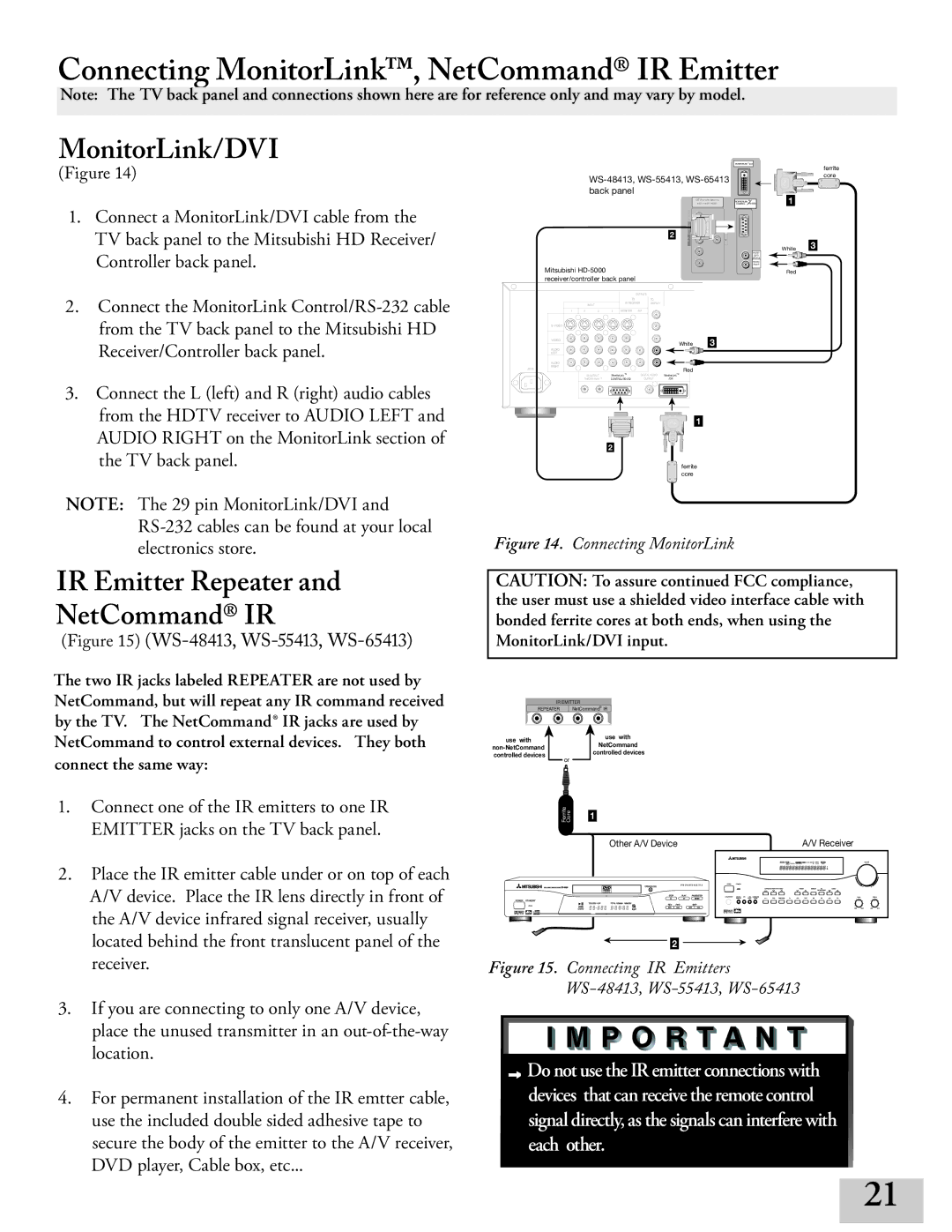
MonitorLink/DVI
(Figure 14)
1.Connect a MonitorLink/DVI cable from the TV back panel to the Mitsubishi HD Receiver/ Controller back panel.
2.Connect the MonitorLink
3.Connect the L (left) and R (right) audio cables from the HDTV receiver to AUDIO LEFT and AUDIO RIGHT on the MonitorLink section of the TV back panel.
|
|
| ||||||||
|
|
| back panel |
|
|
|
|
| ||
|
|
|
|
|
|
|
|
|
| DTV(YPbPr/ GBRHV ) |
|
|
|
|
|
|
|
|
|
| 480i / 480P /1080 i |
|
|
|
|
|
|
|
|
| Y |
|
|
|
|
|
|
|
|
|
| G | 403XF- |
|
|
|
|
|
|
|
|
| B | |
|
|
|
|
|
|
|
| 2 | Pb |
|
|
|
|
|
|
|
|
| P r | 5K | |
|
|
|
|
|
|
|
|
| R | V |
| Mitsubishi |
|
|
|
|
|
|
| ||
| receiver/controller back panel |
|
|
|
|
| ||||
|
|
|
|
|
| OUTPUTS |
|
|
| |
|
|
|
|
| TO |
| TO |
|
|
|
|
|
| INPUT |
| AV RECEIVER | DISPLAY |
|
|
| |
|
|
|
|
|
|
|
|
|
| |
| 1 | 2 | 3 | 4 | MONITOR | PIP |
|
|
| |
|
|
|
|
|
|
|
|
|
| |
| VIDEO |
|
|
|
|
|
|
| White | 3 |
|
|
|
|
|
|
|
|
| ||
| AUDIO |
|
|
|
|
|
|
|
|
|
| LEFT |
|
|
|
|
|
|
|
|
|
| AUDIO |
|
|
|
|
|
|
|
|
|
AC IN | RIGHT |
|
|
|
|
|
|
| Red |
|
|
|
| IR OUTPUT | MonitorLink TM |
| DIGITAL AUDIO | MonitorLinkTM |
|
| |
|
| NetCommand R |
| OUTPUT | /DVI |
|
| |||
|
|
|
|
|
|
|
|
| 1 | |
|
|
|
| 2 |
|
|
|
|
|
|
|
|
|
|
|
|
|
|
| ferrite | |
|
|
|
|
|
|
|
|
| core |
|
MONITORLINK | /DVI | ferrite |
|
| |
|
| core |
MONITORLINK | 1 | |
CONTROL |
White 3
AUDIO-
LEFT/
(MONO)
AUDIO-
RIGHT
Red
NOTE: The 29 pin MonitorLink/DVI and
IR Emitter Repeater and
NetCommand® IR
(Figure 15) (WS-, WS-, WS-)
The two IR jacks labeled REPEATER are not used by NetCommand, but will repeat any IR command received by the TV. The NetCommand® IR jacks are used by NetCommand to control external devices. They both connect the same way:
1.Connect one of the IR emitters to one IR EMITTER jacks on the TV back panel.
2.Place the IR emitter cable under or on top of each A/V device. Place the IR lens directly in front of the A/V device infrared signal receiver, usually located behind the front translucent panel of the receiver.
3.If you are connecting to only one A/V device, place the unused transmitter in an
4.For permanent installation of the IR emtter cable, use the included double sided adhesive tape to secure the body of the emitter to the A/V receiver, DVD player, Cable box, etc...
Figure 14. Connecting MonitorLink
CAUTION: To assure continued FCC compliance, the user must use a shielded video interface cable with bonded ferrite cores at both ends, when using the MonitorLink/DVI input.
IR EMITTER
REPEATER | NetCommandR IR |
use with |
|
|
| use with |
|
|
| NetCommand | |
|
|
| ||
|
|
| controlled devices | |
controlled devices |
|
|
| |
| or |
|
| |
|
|
|
|
Ferrite Core | 1 |
|
| Other A/V Device |
|
|
| A/V Receiver | |||
|
|
|
|
|
|
|
|
|
|
|
|
|
|
|
|
|
|
|
|
|
|
|
|
|
|
|
|
|
|
|
|
|
|
|
|
|
|
|
|
|
|
|
|
|
|
|
|
|
|
|
|
|
|
|
|
|
|
|
|
|
|
|
|
|
|
|
|
|
|
2
Figure 15. Connecting IR Emitters WS-48413, WS-55413, WS-65413
![]() Do not use the IR emitter connections with devices that can receive the remote control signal directly, as the signals can interfere with each other.
Do not use the IR emitter connections with devices that can receive the remote control signal directly, as the signals can interfere with each other.
21