Chapter 6. Specifications and Accessories
Cable Pin Outs –––––––––––––––––––––––––––––––––––––––––––––
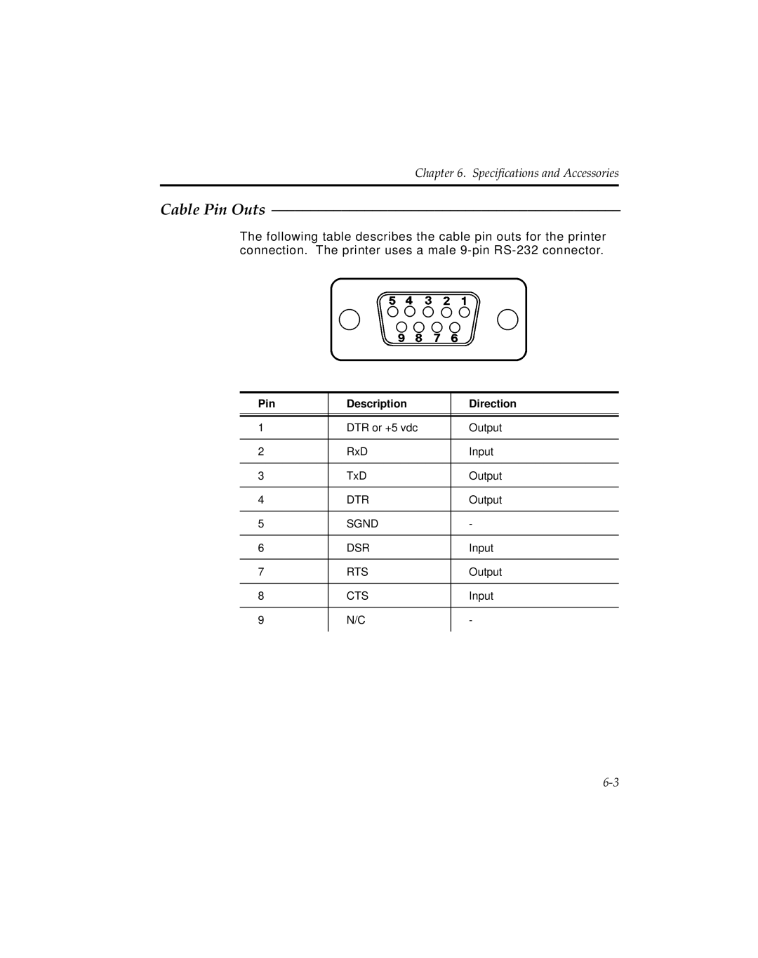
The following table describes the cable pin outs for the printer connection. The printer uses a male
Pin | Description | Direction |
|
|
|
|
|
|
1 | DTR or +5 vdc | Output |
|
|
|
2 | RxD | Input |
|
|
|
3 | TxD | Output |
|
|
|
4 | DTR | Output |
|
|
|
5 | SGND | - |
|
|
|
6 | DSR | Input |
|
|
|
7 | RTS | Output |
|
|
|
8 | CTS | Input |
|
|
|
9 | N/C | - |
|
|
|
