ELECTRICAL WIRING
The
OPERATE.
Wall
Switch
On/Off
Switch
WARNING | Label all wires prior to disconnection |
operation after servicing. | |
| when servicing controls. Wiring |
| errors can cause improper and |
| dangerous operation. Verify proper |
ODS
Pilot
On/Off
Switch
ODS
Pilot
Valve
Spade
Terminal
TH = 3
TP = 1
TP/TH = 2
Switch
| Optional Wall | |
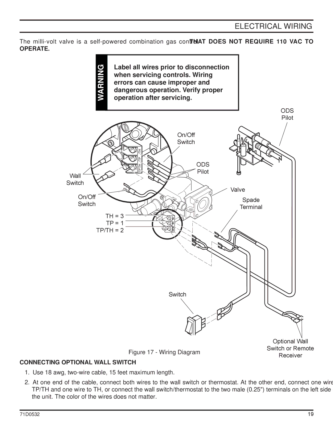
Figure 17 - Wiring Diagram | Switch or Remote | |
Receiver | ||
|
CONNECTING OPTIONAL WALL SWITCH
1.Use 18 awg, two-wire cable, 15 feet maximum length.
2.At one end of the cable, connect both wires to the wall switch or thermostat. At the other end, connect one wire to TP/TH and one wire to TH, or connect the wall switch/thermostat to the two male (0.25") terminals on the left side of the unit. The color of the wires does not matter.
71D0532 | 19 |
