Radio Disassembly — Detailed |
6.Insert the Chassis Opener at the bottom of the radio, between the chassis and housing (see “Figure
7.Lift rear chassis away from the front cover. Be careful not to damage the speaker wire under- neath.
Speaker Wire
Figure
8.Slide the rear chassis downwards, and away from the front cover.
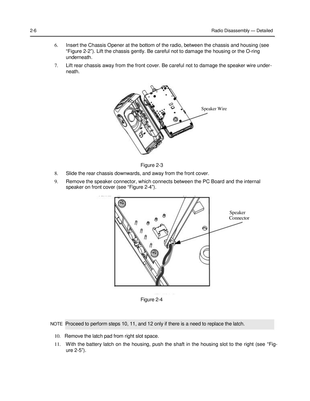
9.Remove the speaker connector, which connects between the PC Board and the internal speaker on front cover (see “Figure
Speaker
Connector
Figure
NOTE Proceed to perform steps 10, 11, and 12 only if there is a need to replace the latch.
10.Remove the latch pad from right slot space.
11.With the battery latch on the housing, push the shaft in the housing slot to the right (see “Fig- ure