Hardware Tuning Setup and Procedure |
5.Then adjust R216 counterclockwise at the point where the Audio Frequency signal appears.
2.4.3PLL Synthesizer Tuning Rx PLL Frequency Tuning
1.Set the radio to the appropriate tuning frequency (refer Table
2.Detect output voltage at test point TP1 (refer to Figure
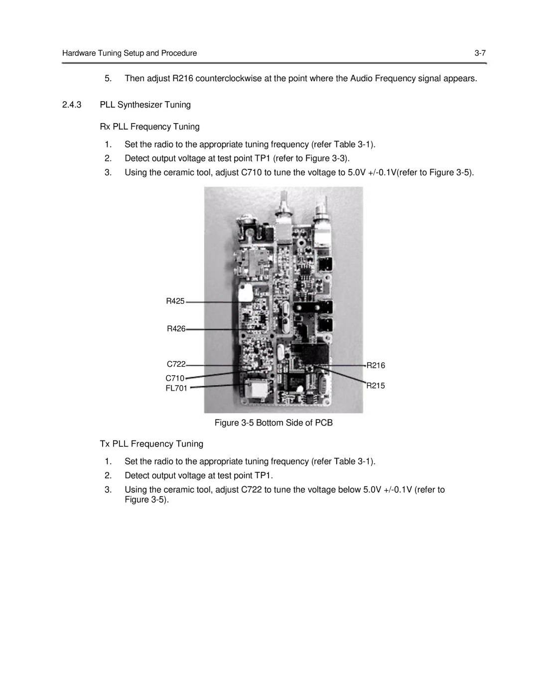
3.Using the ceramic tool, adjust C710 to tune the voltage to 5.0V
R425 |
|
R426 |
|
C722 | R216 |
C710 |
|
FL701 | R215 |
|
