Hardware Tuning Setup and Procedure |
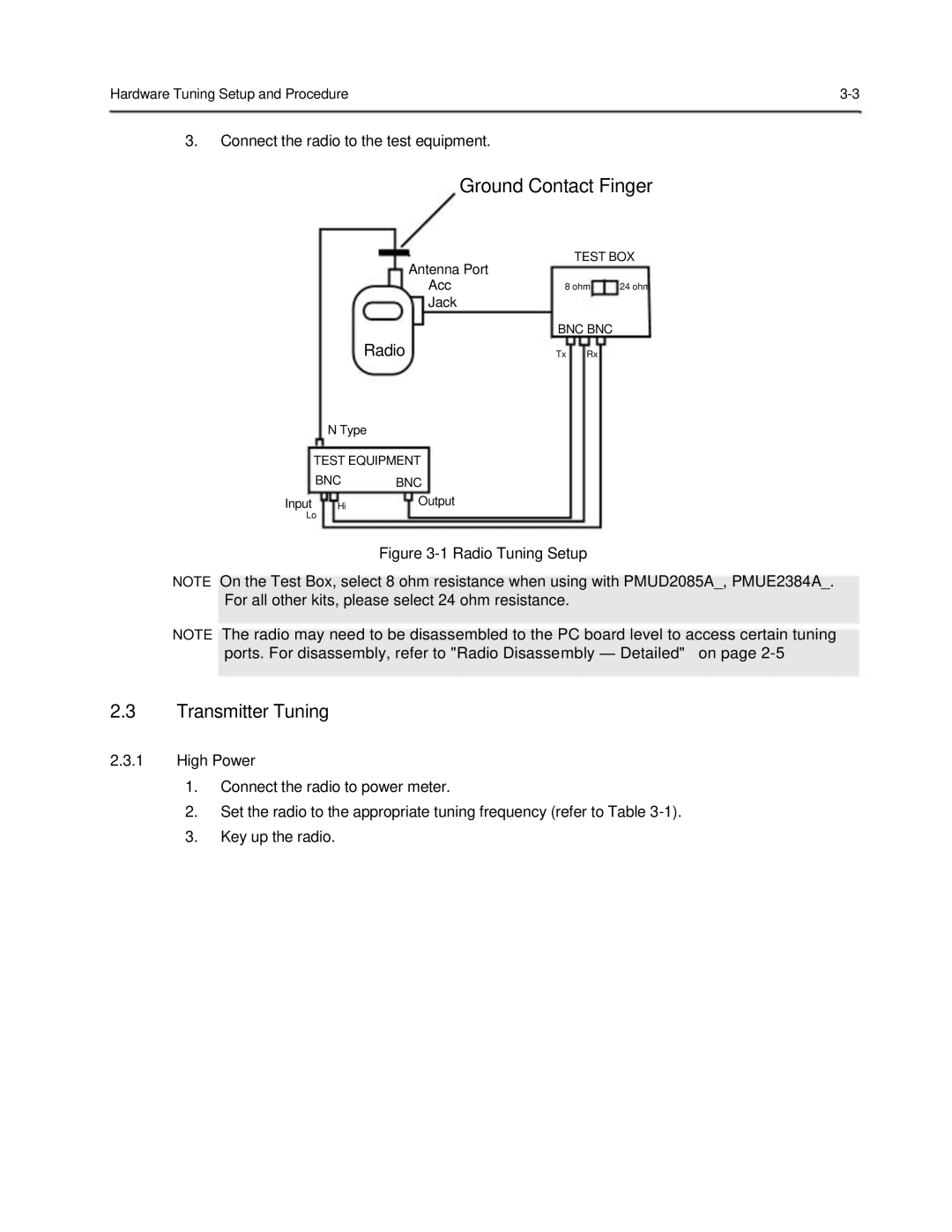
3.Connect the radio to the test equipment.
Ground Contact Finger
TEST BOX
Antenna Port
Acc | 8 ohm | 24 ohm |
Jack |
|
|
| BNC BNC |
|
Radio | Tx Rx |
|
N Type
TEST EQUIPMENT
BNC | BNC |
Input Hi | Output |
Lo |
|
Figure 3-1 Radio Tuning Setup
NOTE On the Test Box, select 8 ohm resistance when using with PMUD2085A_, PMUE2384A_. For all other kits, please select 24 ohm resistance.
NOTE The radio may need to be disassembled to the PC board level to access certain tuning
ports. For disassembly, refer to "Radio Disassembly — Detailed" on page 2-5
2.3Transmitter Tuning
2.3.1High Power
1.Connect the radio to power meter.
2.Set the radio to the appropriate tuning frequency (refer to Table
3.Key up the radio.