10 Getting Started (cont.)
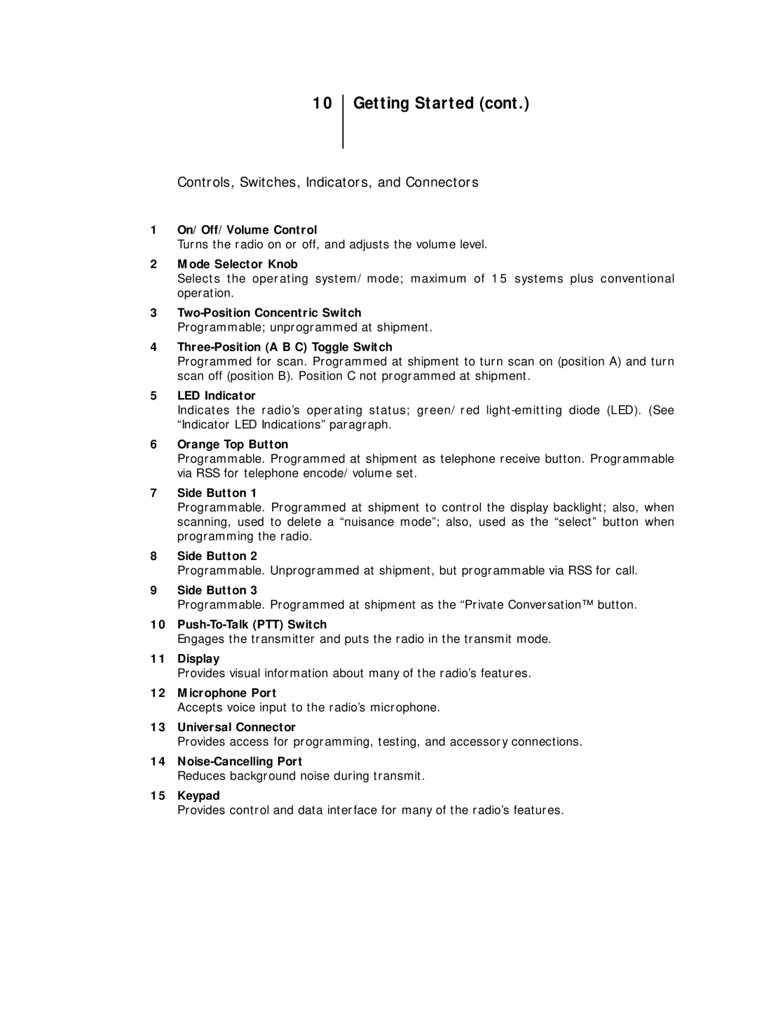
Controls, Switches, Indicators, and Connectors
1On/Off/Volume Control
Turns the radio on or off, and adjusts the volume level.
2Mode Selector Knob
Selects the operating system/mode; maximum of 15 systems plus conventional operation.
3
4
Programmed for scan. Programmed at shipment to turn scan on (position A) and turn scan off (position B). Position C not programmed at shipment.
5LED Indicator
Indicates the radio’s operating status; green/red
6Orange Top Button
Programmable. Programmed at shipment as telephone receive button. Programmable via RSS for telephone encode/volume set.
7Side Button 1
Programmable. Programmed at shipment to control the display backlight; also, when scanning, used to delete a “nuisance mode”; also, used as the “select” button when programming the radio.
8Side Button 2
Programmable. Unprogrammed at shipment, but programmable via RSS for call.
9Side Button 3
Programmable. Programmed at shipment as the “Private Conversation™ button.
10
Engages the transmitter and puts the radio in the transmit mode.
11Display
Provides visual information about many of the radio’s features.
12Microphone Port
Accepts voice input to the radio’s microphone.
13Universal Connector
Provides access for programming, testing, and accessory connections.
14
Reduces background noise during transmit.
15Keypad
Provides control and data interface for many of the radio’s features.
