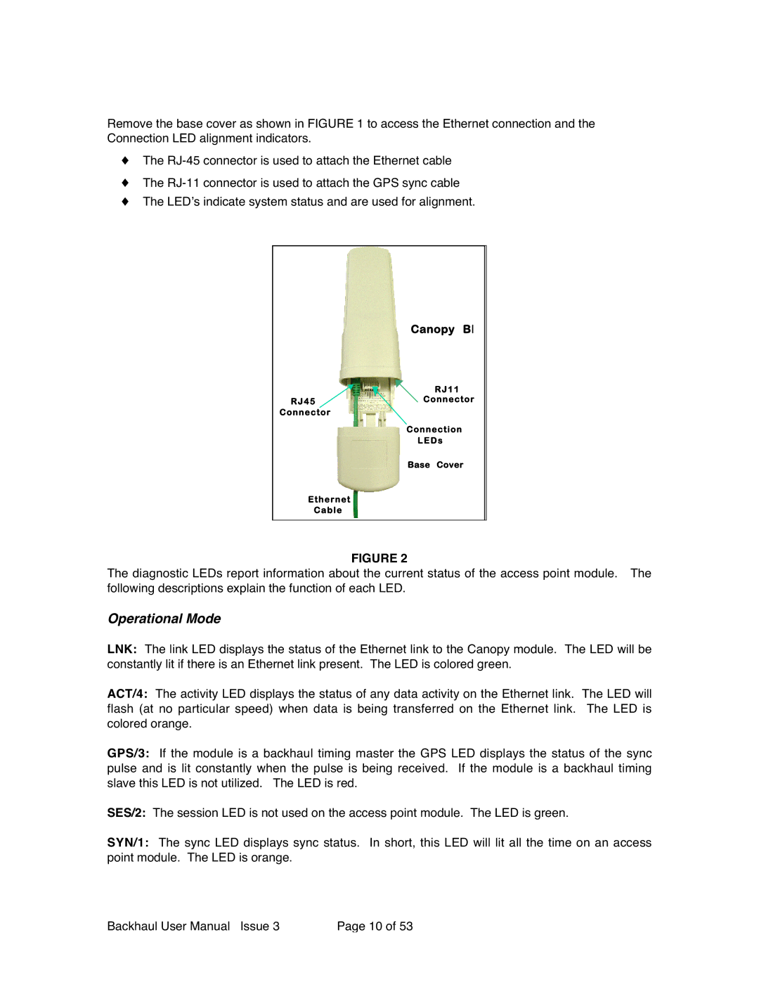
Remove the base cover as shown in FIGURE 1 to access the Ethernet connection and the Connection LED alignment indicators.
♦The
♦The
♦The LED’s indicate system status and are used for alignment.
Canopy BH
RJ11
RJ45Connector
Connector
Connection
LEDs
Base Cover
Ethernet
Cable
FIGURE 2
The diagnostic LEDs report information about the current status of the access point module. The following descriptions explain the function of each LED.
Operational Mode
LNK: The link LED displays the status of the Ethernet link to the Canopy module. The LED will be constantly lit if there is an Ethernet link present. The LED is colored green.
ACT/4: The activity LED displays the status of any data activity on the Ethernet link. The LED will flash (at no particular speed) when data is being transferred on the Ethernet link. The LED is colored orange.
GPS/3: If the module is a backhaul timing master the GPS LED displays the status of the sync pulse and is lit constantly when the pulse is being received. If the module is a backhaul timing slave this LED is not utilized. The LED is red.
SES/2: The session LED is not used on the access point module. The LED is green.
SYN/1: The sync LED displays sync status. In short, this LED will lit all the time on an access point module. The LED is orange.
Backhaul User Manual Issue 3 | Page 10 of 53 |