S e t u p 2 : C a b l e B o x o r S a t e l l i t e R e c e i v e r
1. | Check that the cable from the wall is connected to the cable or satellite box. |
2. | Connect the Composite A/V cable from the Audio/Video Output connectors on the |
| cable or satellite box to the Audio/Video Input 1 connectors on the Recorder. |
3. | Connect the Composite A/V cable from the Audio/Video Output 1 connectors on the |
| Recorder to the Audio/Video Input connectors on the TV. |
4. | Connect a phone line (see page 8 for help). After you complete Guided Setup (see step |
| 10 below), you’ll be able to connect your Recorder to a home network and use a shared |
| broadband Internet connection instead of a phone line to connect to the TiVo service. |
| See Chapter 8, “Connecting to a Home Network,” in the User’s Guide. |
5. | Select a channel changing Control cable (see page 9 for help). You can use the Serial |
| Control cable if you have a DIRECTV satellite receiver with a |
| a Motorola/General Instruments DCT2000 series cable box. If you choose the Serial |
| Control cable, continue with step 6. For any other satellite receiver or cable box, |
| choose the IR Control cable and skip to step 7. |
6. | Connect the Serial Control cable. Plug one end of the Serial Control cable into the |
| Data connector on the satellite receiver or cable box. Plug the other end into the |
2
For tips on the IR Control cable ® connection, see page 10.
IR Control cable connection
7
extends 1½ "
Channel Change/Serial connector (the lower |
to step 10. |
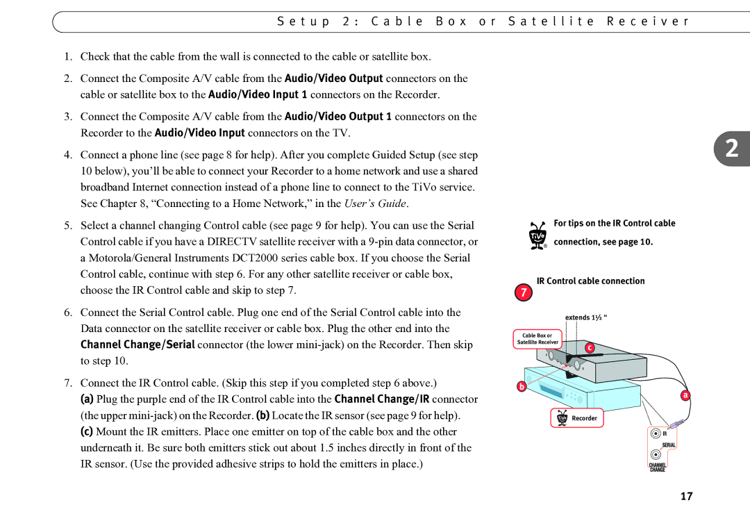
7. Connect the IR Control cable. (Skip this step if you completed step 6 above.) |
(a) Plug the purple end of the IR Control cable into the Channel Change/IR connector |
(the upper |
Cable Box or Satellite Receiver
b
c
a
(c) Mount the IR emitters. Place one emitter on top of the cable box and the other |
underneath it. Be sure both emitters stick out about 1.5 inches directly in front of the |
IR sensor. (Use the provided adhesive strips to hold the emitters in place.) |
Recorder
®
17
