Model ST-865M3 SmarTrunk II™ Logic Board

3.2Installation of the ST-865M3 Logic Board

a.Dismantle the radio by first removing the chassis from the front housing. (Refer to section 3.1 instructions for disassembling the radio).
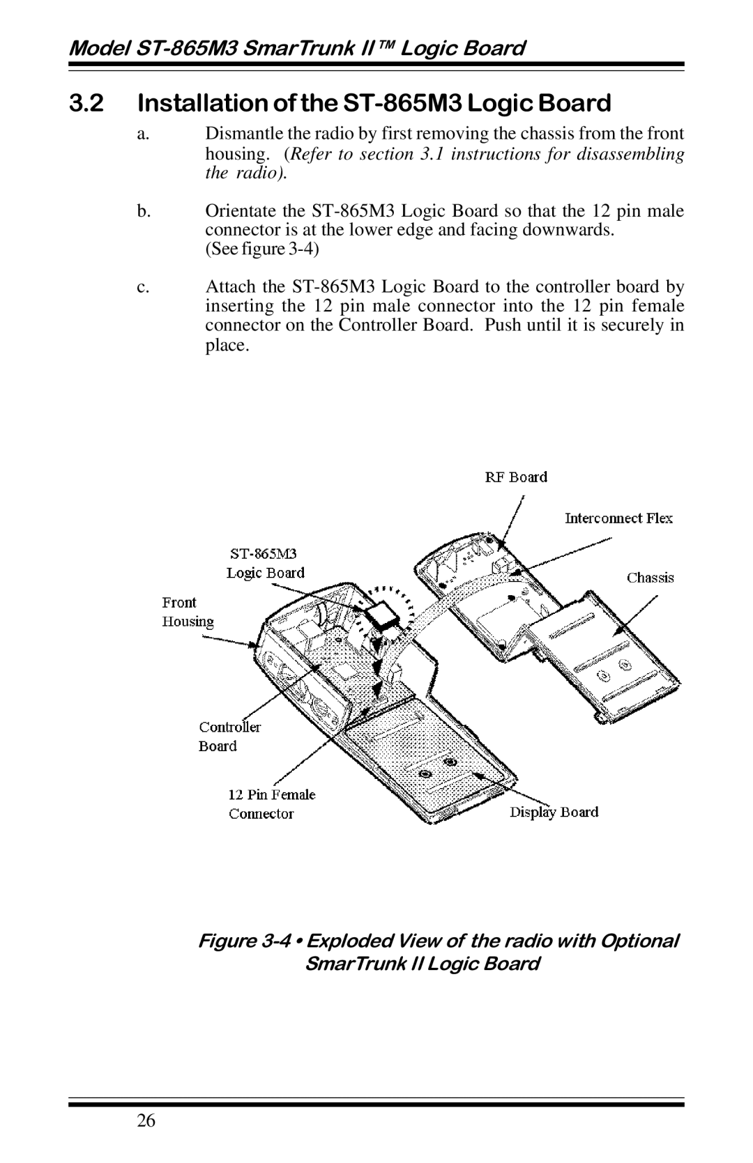
b.Orientate the ST-865M3 Logic Board so that the 12 pin male connector is at the lower edge and facing downwards.

(See figure 3-4)

c.Attach the ST-865M3 Logic Board to the controller board by inserting the 12 pin male connector into the 12 pin female connector on the Controller Board. Push until it is securely in place.

Figure 3-4 • Exploded View of the radio with Optional SmarTrunk II Logic Board

26

Page 26
Image 26
Motorola GP68 operation manual Installation of the ST-865M3 Logic Board, Model ST-865M3 SmarTrunk II Logic Board