Moxa Technologies user manual CP-132UL Series Block Diagram, CP-132UL-I V2 120 x 64.5 mm

Models: CP-132U

1 87
Download 87 pages 49.88 Kb
Page 12
Image 12

CP-132UL Series Block Diagram

CP-132UL Series boards’ hardware configuration for IRQ number and I/O address is automatically assigned by the PCI BIOS. This means that the board MUST be plugged in first before installing the driver software.

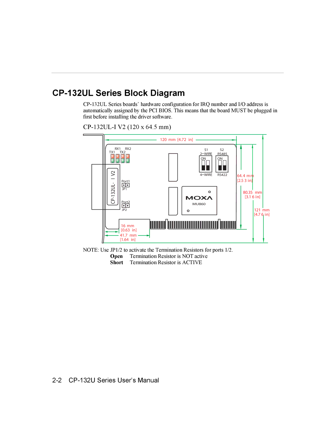
CP-132UL-I V2 (120 x 64.5 mm)

120 mm [4.72 in]

RX1 RX2

TX1 TX2

IV2


-

Port1


132UL-CP

Port2


JP1


JP2

16mm

[0.63 in]

41.7 mm [1.64 in]

S1

2WIRE ON

4 WIRE

MU860

S2

RS485

ON

RS422 64. 4 mm [2.5 3 in]

80.35 mm

[3.1 6 in]

121 mm

[4.7 6 in]

NOTE: Use JP1/2 to activate the Termination Resistors for ports 1/2. Open Termination Resistor is NOT active

Short Termination Resistor is ACTIVE

2-2 CP-132U Series User’s Manual

Page 12
Image 12
Moxa Technologies user manual CP-132UL Series Block Diagram, CP-132UL-I V2 120 x 64.5 mm