Internal Design
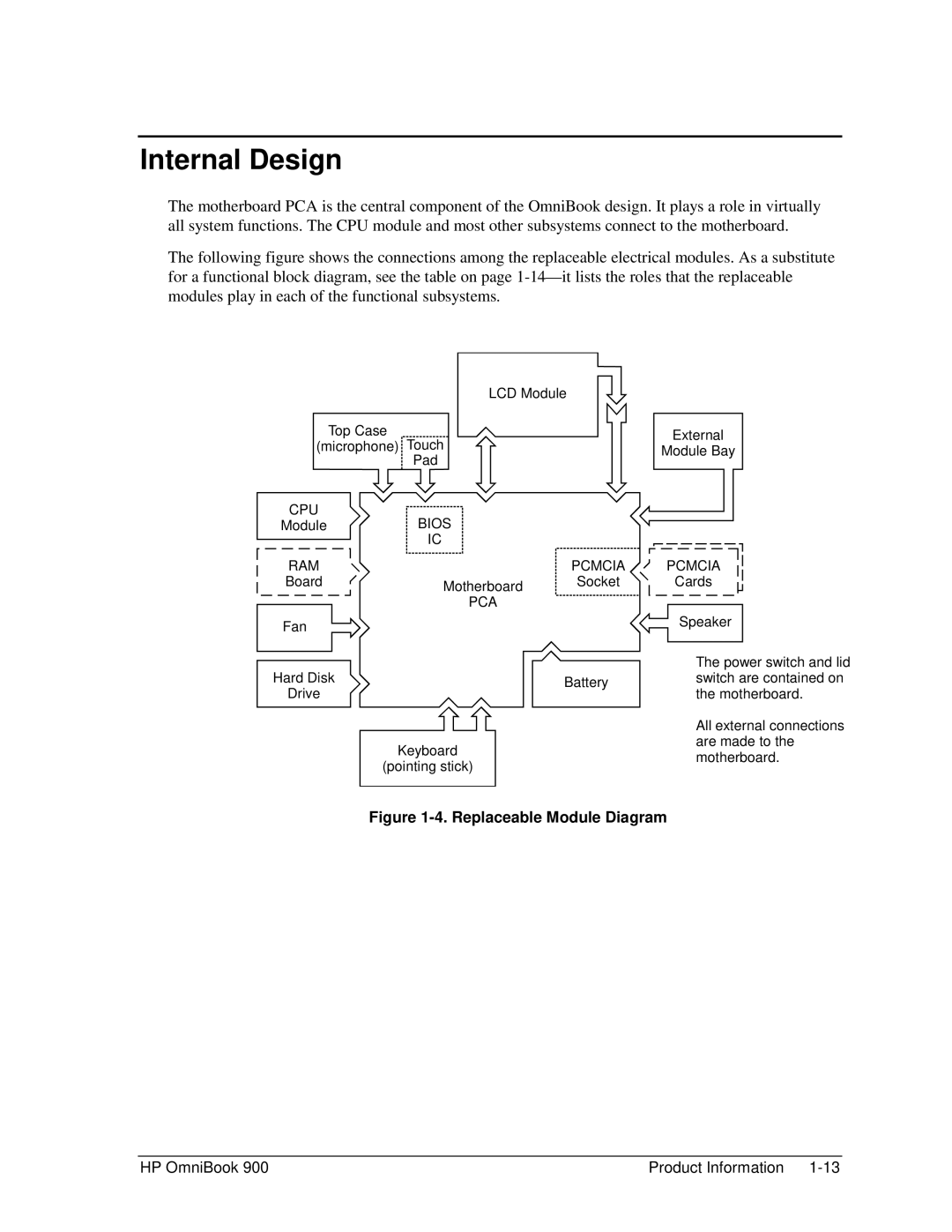
The motherboard PCA is the central component of the OmniBook design. It plays a role in virtually all system functions. The CPU module and most other subsystems connect to the motherboard.
The following figure shows the connections among the replaceable electrical modules. As a substitute for a functional block diagram, see the table on page
|
| LCD Module | |
Top Case | Touch | External | |
(microphone) | |||
Module Bay | |||
| Pad | ||
|
|
|
| CPU | BIOS |
| ||||||||||
Module |
| |||||||||||||
|
|
|
|
|
|
|
|
|
|
|
|
| IC |
|
| RAM |
| PCMCIA | |||||||||||
| Board | Motherboard | Socket | |||||||||||
|
|
|
|
|
|
|
|
|
|
|
|
|
| |
| PCA | |
Fan |
| |
Hard Disk | Battery | |
Drive | ||
| ||
| Keyboard | |
| (pointing stick) |
PCMCIA
Cards
Speaker
The power switch and lid switch are contained on the motherboard.
All external connections are made to the motherboard.
Figure 1-4. Replaceable Module Diagram
HP OmniBook 900 | Product Information |