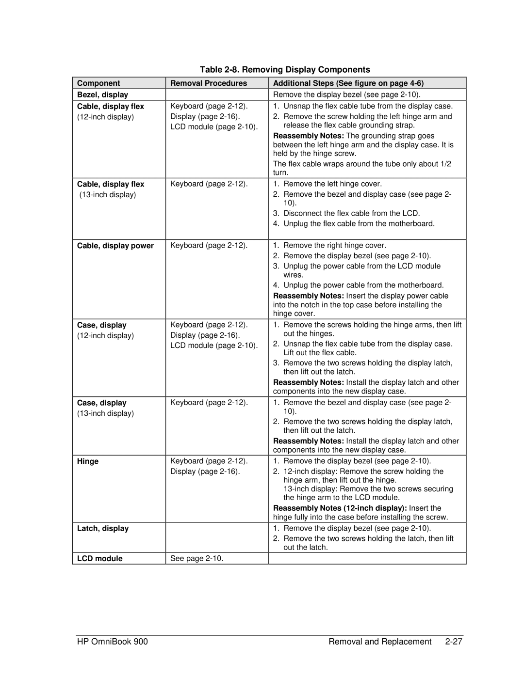
Table 2-8. Removing Display Components
Component
Bezel, display
Cable, display flex
Cable, display flex
Cable, display power
Case, display
Case, display
Hinge
Latch, display
LCD module
Removal Procedures
Keyboard (page
Keyboard (page
Keyboard (page
Keyboard (page
Keyboard (page
Keyboard (page
See page
Additional Steps (See figure on page 4-6)
Remove the display bezel (see page
1.Unsnap the flex cable tube from the display case.
2.Remove the screw holding the left hinge arm and release the flex cable grounding strap.
Reassembly Notes: The grounding strap goes between the left hinge arm and the display case. It is held by the hinge screw.
The flex cable wraps around the tube only about 1/2 turn.
1.Remove the left hinge cover.
2.Remove the bezel and display case (see page 2- 10).
3.Disconnect the flex cable from the LCD.
4.Unplug the flex cable from the motherboard.
1.Remove the right hinge cover.
2.Remove the display bezel (see page
3.Unplug the power cable from the LCD module wires.
4.Unplug the power cable from the motherboard.
Reassembly Notes: Insert the display power cable into the notch in the top case before installing the hinge cover.
1.Remove the screws holding the hinge arms, then lift out the hinges.
2.Unsnap the flex cable tube from the display case. Lift out the flex cable.
3.Remove the two screws holding the display latch, then lift out the latch.
Reassembly Notes: Install the display latch and other components into the new display case.
1.Remove the bezel and display case (see page 2- 10).
2.Remove the two screws holding the display latch, then lift out the latch.
Reassembly Notes: Install the display latch and other components into the new display case.
1.Remove the display bezel (see page
2.
Reassembly Notes
1.Remove the display bezel (see page
2.Remove the two screws holding the latch, then lift out the latch.
HP OmniBook 900 | Removal and Replacement |