Caution: OmniBook 900B
Follow these precautions to prevent damage to the CPU connector:
∙Use only a
∙Use only enough force to lock the CPU module. The CPU connector may be damaged if too much force is used.
To reinstall the CPU assembly, see the precautions under “Reassembly Notes.”
5.For the OmniBook 900B, insert the
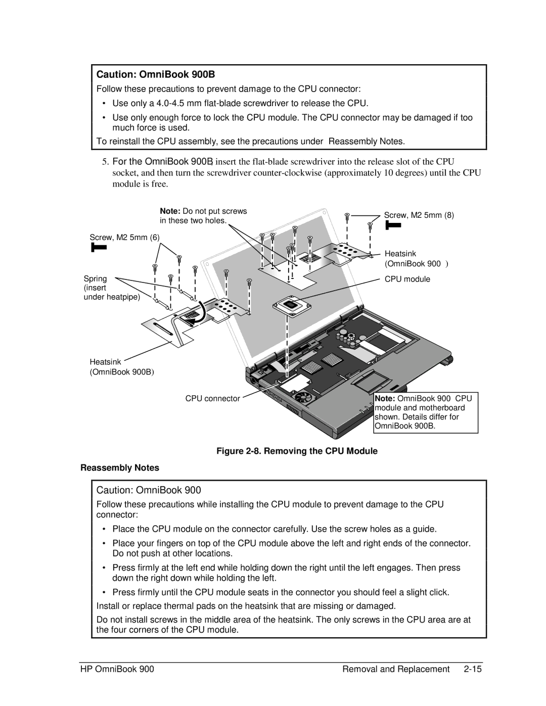
Note: Do not put screws in these two holes.
Screw, M2×5mm (6)
Spring (insert
under heatpipe)
Heatsink (OmniBook 900B)
CPU connector
![]()
![]() Screw, M2×5mm (8)
Screw, M2×5mm (8)
Heatsink (OmniBook 900†)
CPU module
Note:![]()
![]() OmniBook 900† CPU
OmniBook 900† CPU ![]() module and motherboard
module and motherboard
shown. Details differ for OmniBook 900B.
Figure 2-8. Removing the CPU Module
Reassembly Notes
Caution: OmniBook 900†
Follow these precautions while installing the CPU module to prevent damage to the CPU connector:
∙Place the CPU module on the connector carefully. Use the screw holes as a guide.
∙Place your fingers on top of the CPU module above the left and right ends of the connector. Do not push at other locations.
∙Press firmly at the left end while holding down the
∙Press firmly until the CPU module seats in the
Do not install screws in the middle area of the heatsink. The only screws in the CPU area are at the four corners of the CPU module.
HP OmniBook 900 | Removal and Replacement |