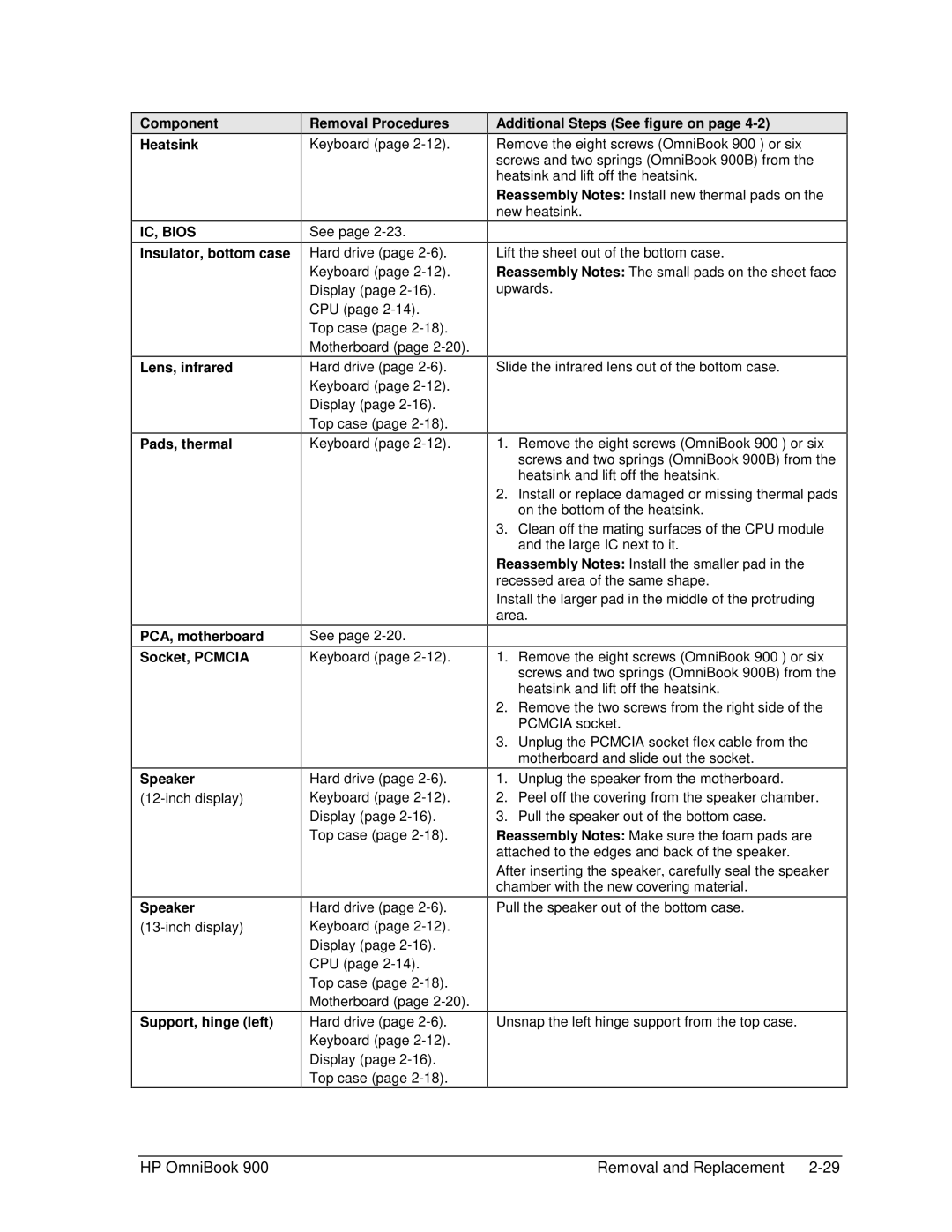
Component
Heatsink
IC, BIOS
Insulator, bottom case
Lens, infrared
Pads, thermal
PCA, motherboard
Socket, PCMCIA
Speaker
Speaker
Support, hinge (left)
Removal Procedures
Keyboard (page
See page
Hard drive (page
CPU (page
Hard drive (page
Top case (page
Keyboard (page
See page
Keyboard (page
Hard drive (page
Top case (page
Hard drive (page
CPU (page
Hard drive (page
Top case (page
Additional Steps (See figure on page 4-2)
Remove the eight screws (OmniBook 900†) or six screws and two springs (OmniBook 900B) from the heatsink and lift off the heatsink.
Reassembly Notes: Install new thermal pads on the new heatsink.
Lift the sheet out of the bottom case.
Reassembly Notes: The small pads on the sheet face upwards.
Slide the infrared lens out of the bottom case.
1.Remove the eight screws (OmniBook 900†) or six screws and two springs (OmniBook 900B) from the heatsink and lift off the heatsink.
2.Install or replace damaged or missing thermal pads on the bottom of the heatsink.
3.Clean off the mating surfaces of the CPU module and the large IC next to it.
Reassembly Notes: Install the smaller pad in the recessed area of the same shape.
Install the larger pad in the middle of the protruding area.
1.Remove the eight screws (OmniBook 900†) or six screws and two springs (OmniBook 900B) from the heatsink and lift off the heatsink.
2.Remove the two screws from the right side of the PCMCIA socket.
3.Unplug the PCMCIA socket flex cable from the motherboard and slide out the socket.
1.Unplug the speaker from the motherboard.
2.Peel off the covering from the speaker chamber.
3.Pull the speaker out of the bottom case.
Reassembly Notes: Make sure the foam pads are attached to the edges and back of the speaker.
After inserting the speaker, carefully seal the speaker chamber with the new covering material.
Pull the speaker out of the bottom case.
Unsnap the left hinge support from the top case.
HP OmniBook 900 | Removal and Replacement |
