ModemModule Developer’s Guide
Test/Demo Board Specifications
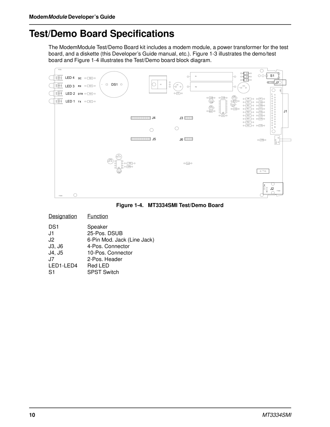
The ModemModule Test/Demo Board kit includes a modem module, a power transformer for the test board, and a diskette (this Developer’s Guide manual, etc.). Figure
LED 4
LED 3 | DS1 |
|
LED 2
LED 1
J4J3
S1
J7
J1
J5J6
J2
| Figure |
Designation | Function |
DS1 | Speaker |
J1 | |
J2 | |
J3, J6 | |
J4, J5 | |
J7 | |
| Red LED |
S1 | SPST Switch |
10 | MT3334SMI |