Chapter 1 - Introduction and Description
Safety: All creepages and clearances for the MT3334SMI have been designed to meet requirements of safety standards EN60950 and IEC950. The requirements are based on a working voltage of 250V. When the recommended DAA circuit interface is implemented in a third party design all creepage and clearance requirements must be strictly adhered to. The third party safety design must be evaluated by the appropriate national agency per the required specification.
User accessible areas: Based on where the third party design is to be marketed/sold or used, it may be necessary to provide an insulating cover over all TNV exposed areas. Consult with the recognized safety agency to determine the requirements.
Notice: Even if the recommended design considerations are followed, there are no guarantees that a particular system will comply with all the necessary regulatory requirements. It is imperative that specific designs be completely evaluated by a qualified/recognized agency.
Recommended Transceiver
Manufacturer – Analog Devices
Part # - ADM207EAR
PC Board Layout Considerations
This section discusses the FCC Part 68 and Industry Canada
This module was tested by the NVLAP accredited KTL Dallas Inc. laboratory and conforms to the above said standards. The modem module was tested in the MultiTech
The
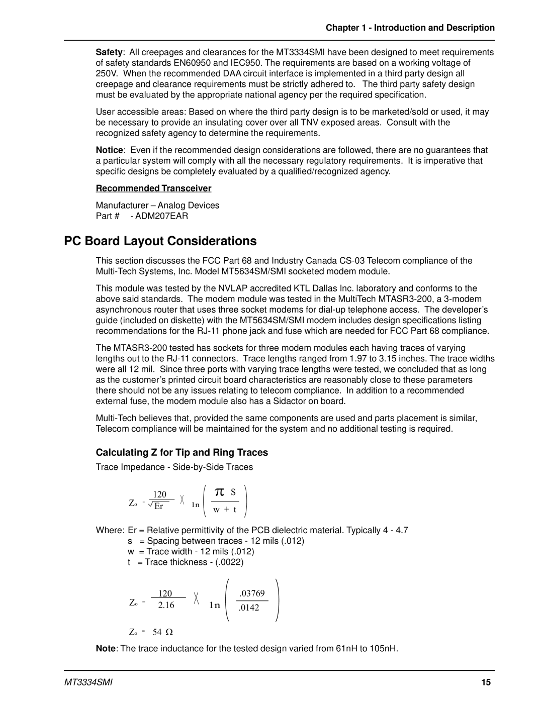
Calculating Z for Tip and Ring Traces
Trace Impedance -
120 |
|
Zo = Er | 1n |
p S
w + t
Where: Er = Relative permittivity of the PCB dielectric material. Typically 4 - 4.7
s= Spacing between traces - 12 mils (.012)
w= Trace width - 12 mils (.012)
t= Trace thickness - (.0022)
Zo |
| 120 |
|
= | 2.16 | 1n | |
Zo | = | 54 W |
|
.03769
.0142
Note: The trace inductance for the tested design varied from 61nH to 105nH.
MT3334SMI | 15 |