ModemModule Developer’s Guide
MT3334SMI Placement
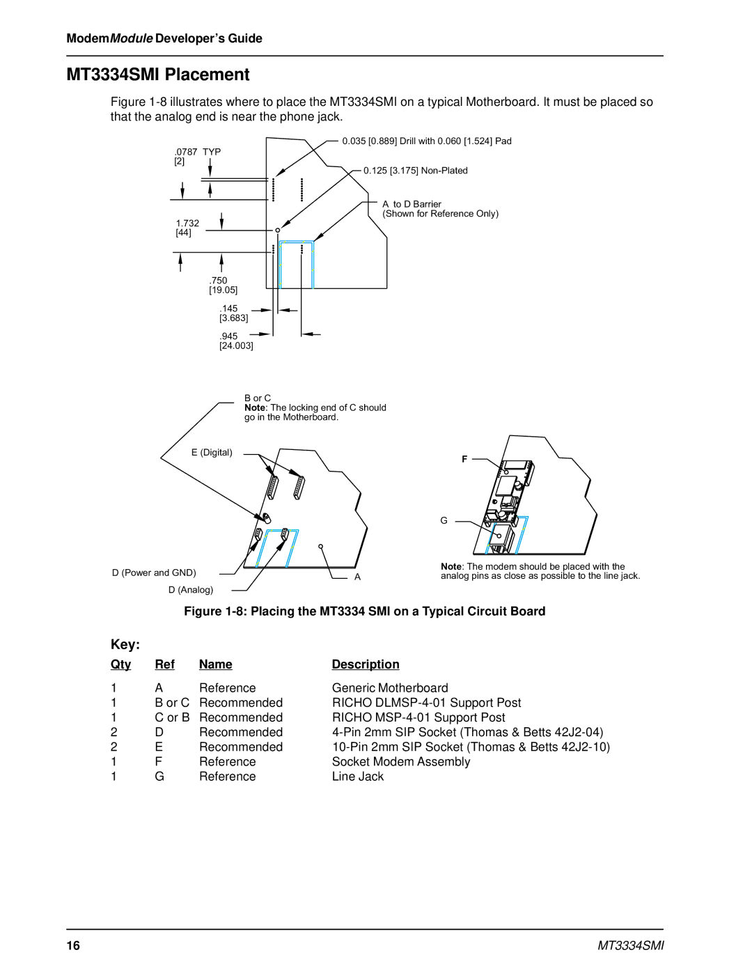
Figure 1-8 illustrates where to place the MT3334SMI on a typical Motherboard. It must be placed so that the analog end is near the phone jack.
0.035 [0.889] Drill with 0.060 [1.524] Pad
.0787 TYP
[2]
0.125 [3.175]
A to D Barrier
(Shown for Reference Only)
1.732
[44]
.750
[19.05]
.145
[3.683]
.945
[24.003]
E (Digital)
D (Power and GND)
D (Analog)
B or C
Note: The locking end of C should go in the Motherboard.
A
F
G
Note: The modem should be placed with the analog pins as close as possible to the line jack.
Figure 1-8: Placing the MT3334 SMI on a Typical Circuit Board
Key:
Qty | Ref | Name | Description |
1 | A | Reference | Generic Motherboard |
1 | B or C | Recommended | RICHO |
1 | C or B | Recommended | RICHO |
2 | D | Recommended | |
2 | E | Recommended | |
1 | F | Reference | Socket Modem Assembly |
1 | G | Reference | Line Jack |
16 | MT3334SMI |