MQ Power Duelweldtm WELDER/AC Generator Model BLW-400SSW
Table of Contents
Heres HOW to GET Help
Table of Contents
USA
Parts Ordering Procedures
Rules for Safe Operation
General Safety
Emergencies
Rules for Safe Operation
Operation and Safety Decals
Operation and Safety Decals
Welder Specifications
BLW-400SSW Specifications
BLW-400SSW General Information
BLW-400SSW Dimensions
BLW-400SSW Dimensions
Explanation of Chart
BLW-400SSW TRAILER-SAFETY Guidelines
TRLR-10XF
BLW-400SSW TRAILER-SPECIFICATIONS
Model Coupler Tires Wheels Axle Hubs
Electric Brakes
BLW-400SSW -TRAILER Safety Guidelines
Electric Brake Adjustment
Brakes
Suspension
BLW-400SSW -TRAILER Safety Guidelines
Tires/Wheels/Lug Nuts
Tire Wear/Inflation
Lug Nut Torque Requirements
Torque Ft.-Lbs
BLW-400SSW -TRAILER-WIRING Diagram
Electric Brake Troubleshooting
BLW-400SSW -TRAILER-BRAKETROUBLESHOOTING
BLW-400SSW -TOWING
Towing Safety Precautions
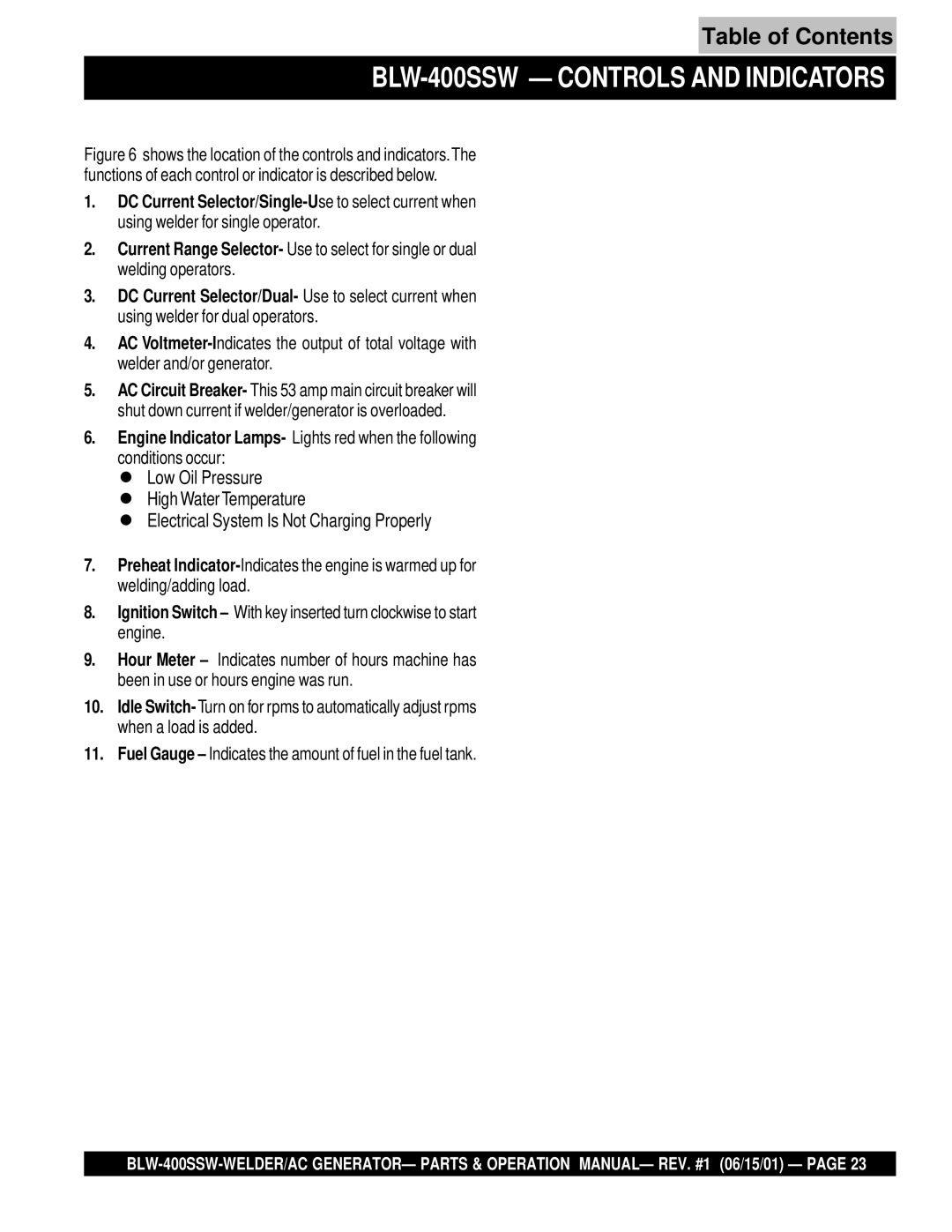
Controls and Indicators
BLW-400SSW Controls and Indicators
BLW-400SSW Controls and Indicators
Volt Receptacle
BLW-400SSW Output Terminal Overview
Maximum Amps
BLW-400SSW Output Terminal Overview
Output Terminal Panel Available Voltages
Outdoor Installation
BLW-400SSW Installation
General Inspection Prior to Operation
BLW-400SSW PRE-SETUP
Lubrication Oil
BLW-400SSW PRE-SETUP
Fan Belt Tension
Cleaning the Radiator
Air Cleaner
Battery
BLW-400SSW Load Application
Single Phase Load
Welding Cables and Polarities
BLW-400SSW- Welder Operating Instructions
Duty Cycle
BLW-400SSW- Welder Operating Instructions
BLW-400SSW- START-UP Instructions
BLW-400SSW- START-UP Instructions
Automatic Idle Control Switch ‘OFF’ position
Emergency Shut-Down
BLW-400SSW Shutdown Instructions
Shutdown
Engine Side
BLW-400SSW Maintenance
Cleaning the Fuel Strainer
General Inspection
Generator Storage
BLW-400SSW Preparation for Long Term Storage
BLW-400SSW -GENERATOR Wiring Diagram
See Previous
BLW-400SSW -ENGINE Wiring Diagram
BLW-400SSW -ENGINE Wiring Diagram
Engine Troubleshooting Part
BLW-400SSW Troubleshooting Engine
BLW-400SSW Troubleshooting Engine
Broken pre-heat circuit? Check pre-heat circuit
BLW-400SSW Troubleshooting Welder
Explanation of Code in Remarks Column
Qty Description
Generator Assy
BLW-400SSW --- Generator Assy
QTY Remarks
BLW-400SSW ---GENERATOR Assy
BLW-400SSW --- Generator Assy
HEX.HEAD Bolt
Control BOX Assy
BLW-400SSW --- Control BOX Assy
Control BOX Assy
BLW-400SSW --- Control BOX Assy
Bttt
BRACKET, Circuit Breaker
Control Parts ASSY. Part
BLW-400SSW --- Control Parts ASSY. Part
BLW-400SSW Control Parts ASSY. Part
BLW-400SSW --- Control Parts ASSY. Part
Fuse Holder
FC90B
Engine and Radiator Assy
BLW-400SSW Engine and Radiator Assy
BLW-400SSW Engine and Radiator Assy
Battery Assy
BLW-400SSW --- Battery Assy
Terminal Assy
Battery Sheet
Battery Bolt
Muffler Assy
BLW-400SSW --- Muffler Assy
BLW-400SSW --- Muffler Assy
Fuel Tank Assy
BLW-400SSW --- Fuel Tank Assy
Tank Sheet
Fuel Tank
CAP, Fuel Tank
BRACKET, Fuel Tank
Enclosure Assy
BLW-400SSW --- Enclosure Assy
BLW-400SSW --- Enclosure Assy
Rubber Seal Assy
BLW-400SSW --- Rubber Seal Assy
BLW-400SSW --- Rubber Seal Assy
Full View
Decal Assy
BLW-400SSW --- Decals
YUASASTCL7B
Decals
Crankcase Assy
Kubota V1205B --- Crankcase Assy
Crankcase Assy
OIL PAN Assy
Kubota V1205B --- OIL PAN Assy
OIL Gauge
Kubota V1205B OIL PAN Assy
Bolt
Cylinder Head Assy
Kubota V1205B --- Cylinder Head Assy
BOLT, Cylinder Head
Kubota V1205B --- Cylinder Head Assy
HOOK, Engine
GUIDE, Inlet Valve
Gear Case Assy
Kubota V1205B --- Gear Case Assy
Gear Case Assy
Main Bearing Case Assy
Kubota V1205B --- Main Bearing Case Assy
BOLT, Bearing Case
Kubota V1205B --- Main Bearing Case Assy
ASSY. CASE, Main BRG
Head Cover Assy
Kubota V1205B --- Head Cover Assy
Kubota V1205B --- Head Cover Assy
Inlet Manifold Assy
Kubota V1205B --- Inlet Manifold Assy
GASKET, IN-MANIFOLD
Kubota V1205B --- Inlet Manifold Assy
JOINT, Breather Pipe
Exhaust Manifold Assy
Kubota V1205B --- Exhaust Manifold Assy
Kubota V1205B Exhaust Manifold Assy
Rocker ARM Valve Assy
Kubota V1205B --- Rocker ARM Valve Assy
Kubota V1205B --- Rocker ARM Valve Assy
Camshaft Assy
Kubota V1205B --- Camshaft Assy
Kubota V1205B Camshaft Assy
Piston Crankshaft Assy
Kubota V1205B--- Piston Crankshaft Assy
Kubota V1205B
Piston Crankshaft Assy
Flywheel Assy
Kubota V1205B --- Flywheel Assy
BOLT, Flywheel
HOUSING, Flywheel
Kubota V1205B Flywheel Assy
Injection Pump Assy
Kubota V1205B --- Injection Pump Assy
CAP NUT
Kubota V1205B Injection Pump Assy
Joint
Injection Pump Shim
Fuel Camshaft Assy
Kubota V1205B --- Fuel Camshaft Assy
Kubota V1205B --- Fuel Camshaft Assy
Nozzle Holder Assy
Kubota V1205B --- Nozzle Holder Assy
Pipe Clamp
Kubota V1205B Nozzle Holder Assy
Pipe Joint
Injection Pipe
Idling Apparatus Assy
Kubota V1205B --- Idling Apparatus Assy
Idling Apparatus Assy
Governor Assy
Kubota V1205B --- Governor Assy
Thrust Lever
Kubota V1205B --- Governor Assy
Start Spring
Governor Spring
Speed Control Plate Assy
Kubota V1205B --- Speed Control Plate Assy
Speed Control Plate Assy
Dynamo Assy
Kubota V1205B --- Dynamo Assy
Dynamo Stay
Kubota V1205B --- Dynamo Assy
Water Flange Assy
Kubota V1205B --- Water Flange Assy
Clamp
Kubota V1205B Water Flange Assy
Thermostat Assy
Water Pipe
Water Pump Assy
Kubota V1205B --- Water Pump Assy
Water Return Pipe
Kubota V1205B Water Pump Assy
FAN Assy
Kubota V1205B --- FAN Assy
FAN Drive Pulley
Kubota V1205B FAN Assy
FAN Pulley
Flange Bolt
Radiator Assy
Kubota V1205B --- Radiator Assy
Pipe Clip
Kubota V1205B Radiator Assy
CAP Assy
Water Over Flow Pipe
AIR Cleaner Assy
Kubota V1205B --- AIR Cleaner Assy
Kubota V1205B AIR Cleaner Assy
Fuel Filter Component Assy
Kubota V1205B --- Fuel Filter Component Assy
Fuel Filter Component
Kubota V1205B Fuel Filter Component Assy
Dynamo Component Assy
Kubota V1205B --- Dynamo Component Assy
Kubota V1205B Dynamo Component Assy
Starter Component Assy
Kubota V1205B --- Starter Component Assy
Starter Component
Kubota V1205B --- Starter Component Assy
Nozzle Holder Component Assy
Kubota V1205B --- Nozzle Holder Component Assy
Kubota V1205B Nozzle Holder Component Assy
Kubota V1205B --- Nozzle Holder Component Assy
1584198810
Injection Pump Components Assy
Kubota V1205B --- Injection Pump Components Assy
Kubota V1205B --- Injection Pump Components Assy
Accessories Assy
Kubota V1205B --- Accessories
Kubota V1205B Accessories
Terms and Conditions of Sale Parts
Effective July 1
Page
Denyo MANUFACTURING, CO., USA