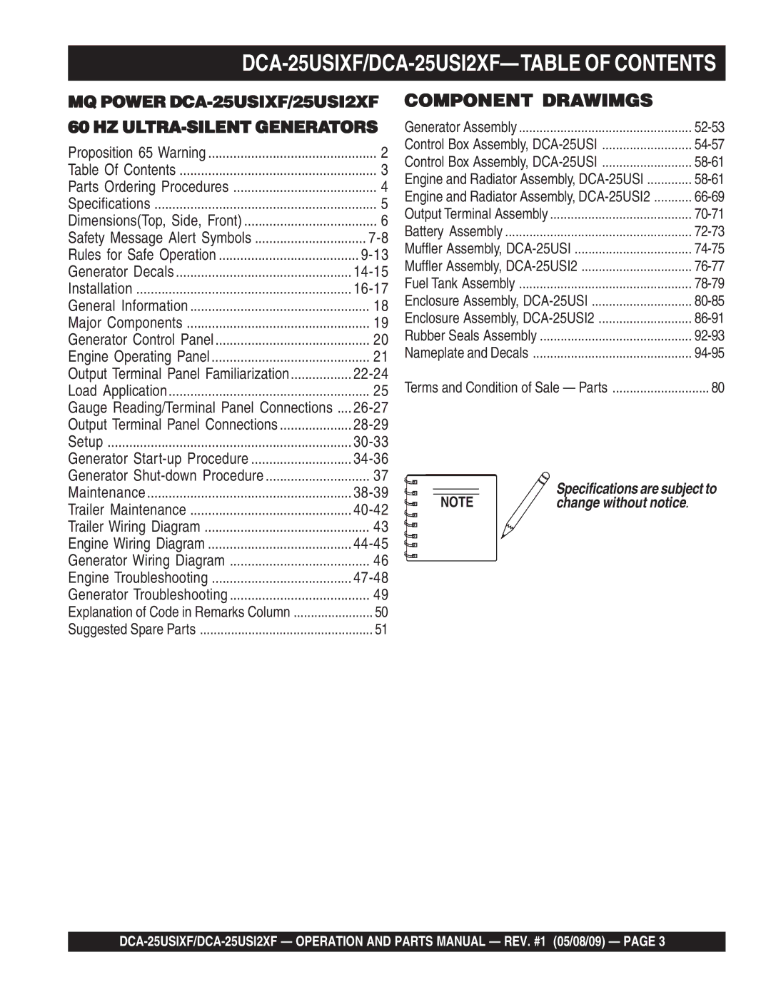
DCA-25USIXF/DCA-25USI2XF—TABLE OF CONTENTS
MQ POWER
60 HZ
Proposition 65 Warning | 2 |
Table Of Contents | 3 |
Parts Ordering Procedures | 4 |
Specifications | 5 |
Dimensions(Top, Side, Front) | 6 |
Safety Message Alert Symbols | |
Rules for Safe Operation | |
Generator Decals | |
Installation | |
General Information | 18 |
Major Components | 19 |
Generator Control Panel | 20 |
Engine Operating Panel | 21 |
Output Terminal Panel Familiarization | |
Load Application | 25 |
Gauge Reading/Terminal Panel Connections .... | |
Output Terminal Panel Connections | |
Setup | |
Generator | |
Generator | 37 |
Maintenance | |
Trailer Maintenance | |
Trailer Wiring Diagram | 43 |
Engine Wiring Diagram | |
Generator Wiring Diagram | 46 |
Engine Troubleshooting | |
Generator Troubleshooting | 49 |
Explanation of Code in Remarks Column | 50 |
Suggested Spare Parts | 51 |
COMPONENT DRAWIMGS
Generator Assembly | |
Control Box Assembly, | |
Control Box Assembly, | |
Engine and Radiator Assembly, | |
Engine and Radiator Assembly, | |
Output Terminal Assembly | |
Battery Assembly | |
Muffler Assembly, | |
Muffler Assembly, | |
Fuel Tank Assembly | |
Enclosure Assembly, | |
Enclosure Assembly, | |
Rubber Seals Assembly | |
Nameplate and Decals | |
Terms and Condition of Sale — Parts | 80 |
NOTE | Specifications are subject to |
change without notice. |
