DCA-25USIXF/DCA-25USI2XF— GENERATOR CONTROL PANEL
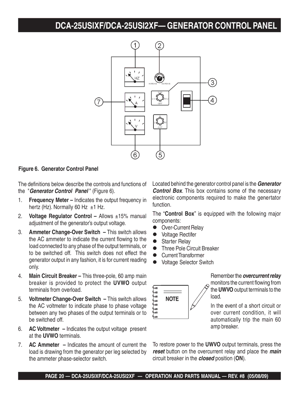
Figure 6. Generator Control Panel
The definitions below describe the controls and functions of the "Generator Control Panel " (Figure 6).
1.Frequency Meter – Indicates the output frequency in hertz (Hz). Normally 60 Hz ±1 Hz.
2.Voltage Regulator Control – Allows ±15% manual adjustment of the generator’s output voltage.
3.Ammeter
4.Main Circuit Breaker – This
5.Voltmeter
6.AC Voltmeter – Indicates the output voltage present at the UVWO terminals.
7.AC Ammeter – Indicates the amount of current the load is drawing from the generator per leg selected by the ammeter
Located behind the generator control panel is the Generator Control Box. This box contains some of the necessary electronic components required to make the genertator function.
The “Control Box” is equipped with the following major components:
Voltage Rectifer
Starter Relay
Three Pole Circuit Breaker
Current Transformer
Voltage Selector Switch
Remember the overcurrent relay monitors the current flowing from the UWVO output terminals to the
NOTE load.
In the event of a short circuit or over current condition, it will automatically trip the main 60 amp breaker.
To restore power to the UWVO output terminals, press the reset button on the overcurrent relay and place the main circuit breaker in the closed position (ON).
PAGE 20 —