DCA-85USJ — GENERATOR START-UP PROCEDURE (MANUAL)
Starting (Manual) | 9. The generator's frequency meter (Figure 45) should be |
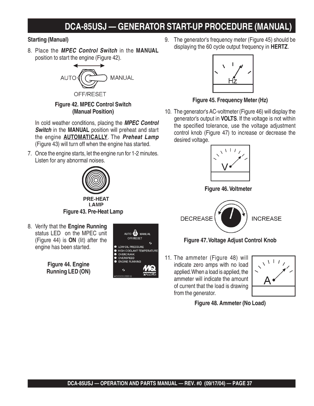
8. Place the MPEC Control Switch in the MANUAL | displaying the 60 cycle output frequency in HERTZ. |
| |
position to start the engine (Figure 42). |
|
Figure 42. MPEC Control Switch
(Manual Position)
In cold weather conditions, placing the MPEC Control Switch in the MANUAL position will preheat and start the engine AUTOMATICALLY. The Preheat Lamp (Figure 43) will turn off when the engine has started.
7.Once the engine starts, let the engine run for
Figure 43. Pre-Heat Lamp
8.Verify that the Engine Running status LED on the MPEC unit (Figure 44) is ON (lit) after the engine has been started.
Figure 44. Engine
Running LED (ON)
Figure 45. Frequency Meter (Hz)
10.The generator's
Figure 46. Voltmeter
Figure 47.Voltage Adjust Control Knob
11.The ammeter (Figure 48) will indicate zero amps with no load applied.When a load is applied, the ammeter will indicate the amount of current that the load is drawing from the generator.