GA-2.5H specifications
The Multiquip GA-2.5H is a robust, portable generator designed to meet the demands of both commercial and residential users. Renowned for its reliability and efficiency, it is an ideal choice for construction sites, outdoor events, and emergency power needs. With a compact design, the GA-2.5H is easy to transport, making it a convenient option for those who require power on-the-go.One of the standout features of the GA-2.5H is its powerful Honda GX160 engine. This four-stroke engine offers a consistent and robust performance, ensuring that the generator can handle various loads without faltering. The engine is also known for its fuel efficiency, allowing users to prolong operational periods and minimize running costs.
The generator provides a maximum output of 2,500 watts, making it suitable for powering essential tools and equipment. Equipped with multiple outlets, including both 120V and 240V options, the GA-2.5H can accommodate various appliances and devices, making it a versatile solution for different power needs.
In terms of durability, the GA-2.5H is built with high-quality materials that can withstand harsh environments. Its heavy-duty frame not only protects the generator components but also ensures stability during operation. Additionally, the unit features a protective circuit breaker that enhances safety by preventing overloads.
Another notable characteristic is its quiet operation. The GA-2.5H is engineered with noise-reduction technologies that significantly lower the sound output, making it ideal for use in noise-sensitive areas. This feature allows users to maintain a peaceful atmosphere, whether at a campsite or a residential neighborhood.
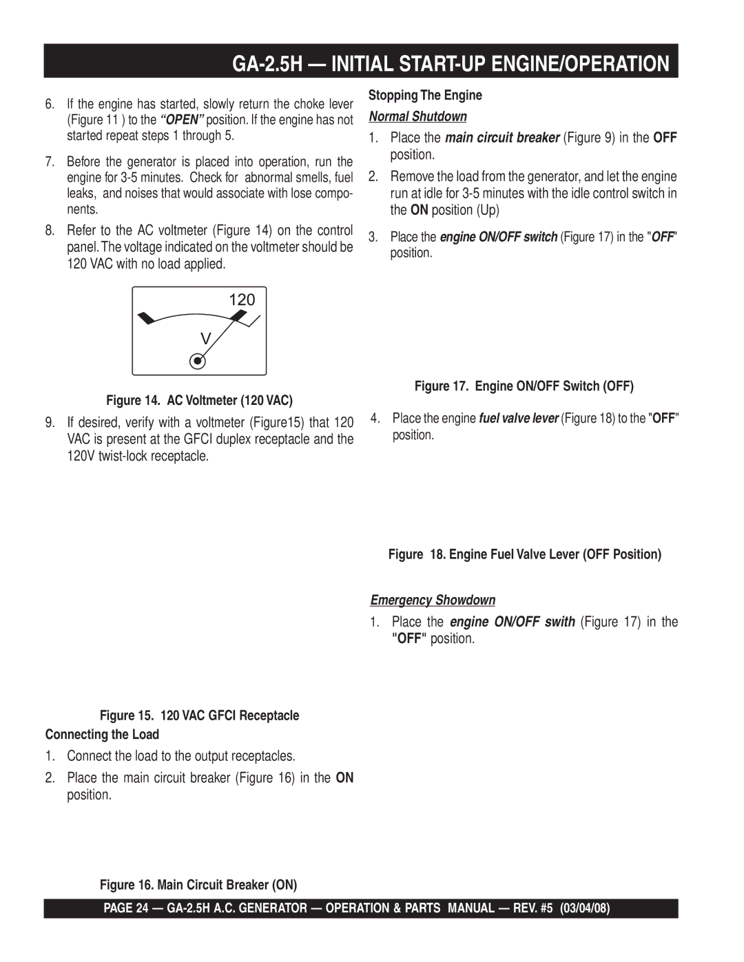
The Multiquip GA-2.5H also incorporates a user-friendly control panel, making it easy for anyone to operate. The panel includes clearly labeled controls and indicators, allowing users to monitor fuel levels, voltage output, and other critical parameters at a glance.
For added convenience, the GA-2.5H comes with a built-in fuel tank that provides extended run times. This larger tank ensures that users can operate the generator for longer periods without the need for frequent refueling.
Overall, the Multiquip GA-2.5H stands out as a powerful, efficient, and portable generator, suitable for a wide range of applications. With its excellent features, durable build, and quiet operation, it is an exceptional choice for anyone in need of reliable power solutions. Whether for construction, emergency backup, or outdoor events, the GA-2.5H delivers performance that users can depend on.

