CONTROLS AND INDICATORS
|
| 23 | 25 | 26 27 |
| 19 |
|
| |
|
|
|
| |
| 18 |
|
| 19 |
| 35 |
|
|
|
28 |
|
|
| 35 |
22 | 17 |
|
| 29 |
|
|
|
|
21
20
30 24
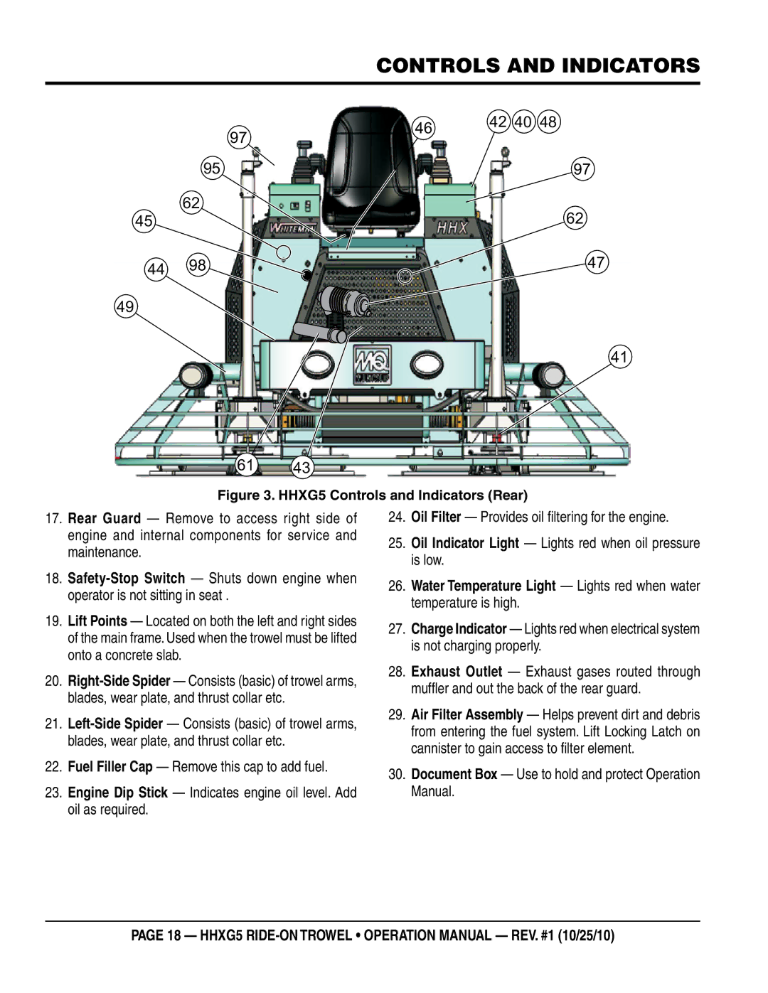
Figure 3. HHXG5 Controls and Indicators (Rear)
17.Rear Guard — Remove to access right side of engine and internal components for service and maintenance.
18.
19.Lift Points — Located on both the left and right sides of the main frame. Used when the trowel must be lifted onto a concrete slab.
20.
21.
22.Fuel Filler Cap — Remove this cap to add fuel.
23.Engine Dip Stick — Indicates engine oil level. Add oil as required.
24.Oil Filter — Provides oil filtering for the engine.
25.Oil Indicator Light — Lights red when oil pressure is low.
26.Water Temperature Light — Lights red when water temperature is high.
27.Charge Indicator — Lights red when electrical system is not charging properly.
28.Exhaust Outlet — Exhaust gases routed through muffler and out the back of the rear guard.
29.Air Filter Assembly — Helps prevent dirt and debris from entering the fuel system. Lift Locking Latch on cannister to gain access to filter element.
30.Document Box — Use to hold and protect Operation Manual.
page 18 — HHXg5