Model HTH44T
Proposition 65WARNING
SILICOSIS/RESPIRATORYWARNINGS
HTH44T-TABLE of Contents
Parts Ordering Procedures
Ordering parts has never been easier
HTH44T-TRAINING Checklist
Training Checklist
HTH44T- Daily PRE-OPERATION Checklist
Daily PRE-OPERATION Checklist
HTH44T- Safety Message Alert Symbols
HTH44T- Safety Message Alert Symbols
Over Speed Conditions Sight and Hearing hazard
HTH44T- Rules for Safe Operation
HTH44T- Operation and Safety Decals
HTH44T- Specifications
HTH-44T Specifications
HTH44T- General Information
HTH44T- Controls and Indicators
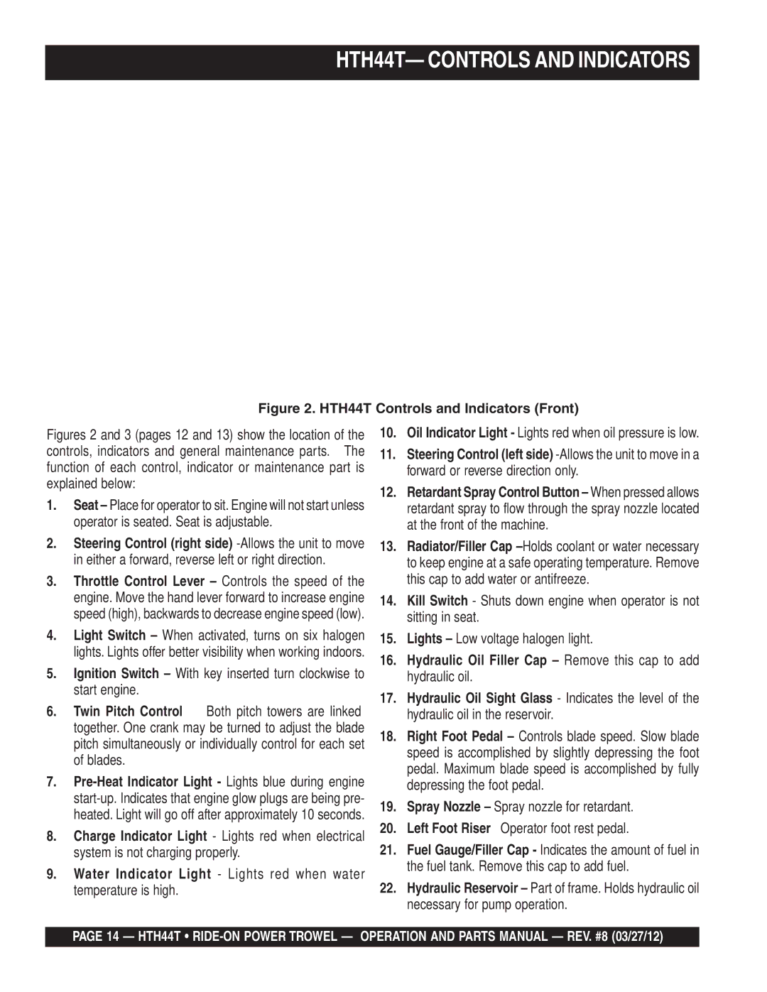
HTH44T Controls and Indicators Front
HTH44T Controls and Indicators Rear
HTH44T- Initial START-UP
Fuel
HTH44T- Initial START-UP
Engine Throttle Control Lever High
Joystick Control Forward Direction
HTH44T- Maintenance
Maintenance Schedule
Blade Pitch Adjustment Procedure
Changing a Blade
Pressure Gauge Hydraulic Pump
Pressure Gauge Left Steering Valve
Steering Pressure Adjustment
HTH44T-TROUBLESHOOTING
Wiring?
HTH44T- Explanation of Code in Remarks Column
Unit
HTH44T- Pivot ASSY. Left
Pivot ASSY. Left
Rocker Block
Yoke
Bushing
WASHER, Lock 3/8 MED
HTH44T- Pivot ASSY. Right
Pivot ASSY. Right
SHAFT, Pivot
Trunnion
RETAINER, Clutch
HTH44T-TWIN Pitch ASSY. LEFT/RIGHT
LEFT/RIGHT Twin Pitch Assy
HTH44T-TWIN Pitch ASSY. LEFT/RIGHT
KEY, Woodruff #9
HOUSING, Pitch CONTROL, 1-3/4
COVER, Pitch Cont Housing
WASHER, Lock 5/16 MED
SET COLLAR, 1/2
WASHER, FLAT, 5/16 SAE
SLEEVE, W/U-JOINT
Miter BOX, Pitch Control
HTH44T- Engine Kubota
Engine Kubota
WASHER, LOCK, 1/2 MED
HOSE, AIR Cleaner
ELEMENT, AIR Cleaner
SCREW, Drive #2- 3/16 U- Drive
HTH44T- Engine Flange Kubota
HUB, Hydraulic Pump
Bell HOUSING, KTR
FLANGE, Nylon
MOUNT, Right Motor
HTH44T- Engine Fuel Kubota
Engine Fuelkubota
FILTER, Cannister Fuel
WASHER, LOCK, 7/16 MED
HTH44T- Hydraulic Steering Left
Hydraulic Steering Left
BELLOWS, STG. Cylinder
TUBE, HYD. Steering Pressure
TUBE, HYD. Steering Return
PLATE, Bellows Mounting
HTH44T- Hydraulic Steering Right
Hydraulic Steering Right
Hose ASM, .38 ID X 15.5 STR. Ends
Hose ASM, .38 ID X 17 STR Ends
FITTING, 45 6MJ- 6MO
NUT, HEX JAM Blkhd .5625-18UNF
Steering Valve Assembly Left
HTH44T- Steering Valve ASSY. Left
NUT, Special
BOOT, Left
CLAMP, Boot
PLATE, Pivot
Steering Valve Assembly Right
FITTING, 45 6MJ-6MO
BOOT, Right
RETAINER, Strg Valve Boot
FITTING, TEE 6MJ-6MO-6MJ
HTH44T- Palm Handles Left and Right
Palm Handles Left and Right
Switch ASM
HANDLE, Palm W/ SWITCH, Left
TUBE, Handle Switch
Valve ASM, Steering Left
HTH44T- Hydraulic Drive Assembly
Hydraulic Drive Assembly
Pump ASM,TANDEM HTH
FITTING, 90 6MJ- 6MO
FITTING, 90 IMP- 3/4FP Swivel
FITING,TEE 12MJ- 12MO- 6FO
Hydraulic Drive Pump Lever Assembly
HTH44T- Hydraulic Drive Pump Lever Assy
NUT, HEX Full 1/4- 28 Left Hand
SPACER, Pump Lever Grommet
GROMMET, Leverminor #Z
ROD, Pump Actuator
HTH44T- Hydraulic Drive Filters and Cooling
Hydraulic Drive Filters and Cooling
CLAMP, 1.1/4 Hose
CONNECTOR, Weatherpack 2 PIN
FITTING, 45 8 Barb X 3/8 MP
FITTING, 45 8BARB X 1/2 MP
Five Blade Spider Assembly Left Side
HTH44T- Five Blade Spider ASSY. Left
Thrust Collar W/ Bushing
SCREW, Trowel Adjustment
PLATE, Wear
Spider ASM,LEFT Side
Five Blade Spider Assembly Right Side
HTH44T- Five Blade Spider ASSY. Right
LEVER, Trowel ARM Right Side
Thrust COLLAR, W/ Bushing
Spider ASM, Right Side
SPRING, Right Trowel
Stabilizer Assembly
HTH44T- Stabilizer Ring Assy
RING, STABILIZER, EXT ARM, HD
WASHER, LOCK, 5/16 MED
HTH44T- Locator Decals
Locator Decals
DECAL, Spring Safety
DECAL, Safety CLOTHING, ISO
DECAL, KEY Switch Lights
DECAL, Engine Speed
HTH44T- TOP Panel Left Assy
TOP Panel Left
Seat Frame
PANEL, Left Front
PANEL, Left Back
COVER, OIL Cooler
HTH44T-TOP Panel Right Assy
TOP Panel Right
Hour Meter
BULB, Indicator Light
WASHER, Lock 1/4 MED
ROD END,10- 32 Female RH
HTH44T- Front Panel Right Assy
Front Panel Right
SWITCH, Ignition W/KEYS
BOOT, Toggle Switch
SWITCH, Toggle ELEC. #9061
Accessory Solenoid
HTH44T- Seat and Frame Assy
Seat and Frame
PLATE, Seat HTH- 44T
FRAME, Seat
Seat W/ ARM Rest
HTH44T- Frame and Fueltank Assy
Frame and Fuel Tank Assy
Fuel CAP/ Gauge
Foot REST, Left
PANEL, Front HTH/STH
SPACER, Fuel Tank
HTH44T- Foot Pedals Assy
Foot Pedals Assy
Accelerator Pedal
Foot REST, Left W/A
CABLE, Throttle ASM
BASE, Speed Control Pedal
HTH44T- Battery Assy
CABLE, NEG Battery Black
Battery Assy
Battery Cable RED
BRACKET, Battery BOX
HTH44T- Spray Assy
Spray Assy
SCREEN, Filter Dapco
FITTING, Plastic Plastic
FITTING, 90 Fuel
TANK, Retardant 5 Gallons
Light Assembly
HTH44T- Light Assy
BRACKET, LIGHT, Left Side
CONNECTOR, Wpack 2PIN Shroud
BRACKET, LIGHT, Right Side
BRACKET, Light
HTH44T-WIRING Diagram
Page
Kubota V-1505 Crankcase Assy
Crankcase Assy
CAP, Sealing
Assembly COCK, Drain
COMP. Crankcase
Plug
Kubota V-1505 OIL PAN Assy
OIL PAN Assy
PLUG, Drain
COMP. OIL PAN
Bolt
FILTER, OIL
Kubota V-1505 Cylinder Head Assy
Cylinder Head Assy
Combustion Chamber
Hook Engine
COMP. Cylinder Head
GUIDE, Inlet Valve
Kubota V-1505 Gear Case Assy
Gear Case Assy
SEAT, Valve
Assembly ROTOR, OIL Pump
COMP. CASE, Gear
Ball
Kubota V-1505 Dipstick and Guide Assy
Dipstick and Guide Assy
Assembly GUIDE, Oilgauge
GAUGE, OIL
Kubota V-1505 Main Bearing Case Assy
Main Bearing Case Assy
GASKET, BRG. Case
Assembly CASE, Main BRG
BOLT, Bearing Case
COVER, Bearing Case
Kubota V-1505 Camshaft and Idle Gear Shaft Assy
Camshaft and Idle Gear Shaft Assy
Push ROD
ASSEMBLY, Camshaft
Tappet
SCREW, SET
Kubota V-1505 Piston and Crankshaft Assy
Piston and Crankshaft Assy
Standard
Assembly ROD, Connecting
BOLT, Connecting ROD
PIN, Piston
Kubota V-1505 Flywheel Assy
Flywheel Assy
PLATE, Rear END
COMP. Flywheel
BOLT, Flywheel
Kubota V-1505 Fuel Camshaft and GOV. Shaft Assy
Fuel Camshaft and Governor Shaft Assy
SHAFT, Governor Weight
HOLDER, Governor Weight
COMP. WEIGHT, Governor
CAMSHAFT, Fuel
Kubota V-1505 Engine Stop Lever Assy
Engine Stop Lever Assy
BOLT, Adjusting
Kubota V-1505 Stop Solenoid Assy
Stop Solenoid Assy
SOLENOID, Stop
BOLT, HEX- SOC- HD
Kubota V-1505 Injection Pump Assy
Injection Pump Assy
JOINT, EYE
Assembly PIPE, Fuel
Assembly PUMP, Injection
CLIP, Pipe
Kubota V-1505 -NOZZLE and Glow Plug Assy
Nozzle Holder and Glow Plug Assy
SEAL, Heat
Assembly HOLDER, Nozzle
SCREW, AIR Breeder
PIPE, Injection
Kubota V-1505 Nozzle Holder Component Parts Assy
Nozzle Holder Component Parts Assy
SPACER, Distance
WASHER, Adjusting
SPRING, Nozzle
NUT, Nozzle
Kubota V-1505 Fork Lever Governor Assy
Fork Lever Governor Assy
SPRING, Governor
Assembly LEVER, Fork
SPRING, Start
LEVER, Fork
Kubota V-1505 Fuel Pump Mechanical Assy
Fuel Pump Mechanical Assy
Assembly PUMP, Fuel
GASKET, Fuel Pump
Kubota V-1505 Altenator and Pully Assy
Alternator and Pulley Assy
Assembly Terminal
Assembly Coupler
Connector
Assembly COUPLER, Lock
Kubota V-1505 Altenator COMP. Parts Assy
Alternator Comonent Parts Assy
Assembly Regulator
Assembly Alernator
Assembly Rectifier
Alternator Component Parts Assy
Kubota V-1505 Starter Assy
Starter Assy
Assembly Starter
Kubota V-1505 Starter Component Parts Assy
Starter Component Partsassy
Assembly Housing
Assembly Yoke
Assembly Clutch
Assembly HOLDER, Brush
Kubota V-1505 OIL SWITCHT/THERMO and Plug Assy
OIL SWITCH/THERMOMETER and Plug Assy
SWITCH, OIL
Kubota V-1505 Waterflang and Thermostat Assy
Water Flange and Thermostat Assy
PIPE, Water Return
Assembly Thermostat
COMP. FLANGE, Water
GASKET, Water Flange
Kubota V-1505 Water Pump Assy
Water Pumpassy
FLANGE, Water Pump
Assembly PUMP, Water
IMPELLER, Water Pump
GASKET, Water Pump
Kubota V-1505 Water Pipe Assy
Water Pipe Assy
PIPE, Water
Clamp
Kubota V-1505 FAN Assy
FAN Assy
COLLAR, FAN
FAN
PULLEY, FAN
Kubota V-1505 Valve and Rocker ARM Assy
Valve and Rocker ARM Assy
VALVE, Inlet
Assembly Rocker ARM
SCREW, Adjusting
VALVE, Exhaust
Kubota V-1505 Inlet Manifold Assy
Inlet Manifold Assy
PIPE, Inlet
Assembly MANIFOLD, Inlet
GASKET, IN- Manifold
Kubota V-1505 Exhaust Manifold Assy
Exhaust Manifold Assy
MANIFOLD, Exhaust
GASKET, EX- Manifold
Kubota V-1505 Turbo Charger Assy
Turbo Charger Assy
Assembly Turbo Charger
FLANGE, Muffler
Kubota V-1505 OIL Pipe Turbo Charger Assy
OIL Pipe Turbo Charger Assy
PIPE, OIL
COMP. PIPE, OIL
BOLT, EYE Joint
CLAMP, Hose
Kubota V-1505 Hydraulic Pump Assy
Hydraulic Pump Assy
COVER, Hydraulic Pump
Kubota V-1505 OIL Cooler Assy
OIL Cooler Assy
Assembly COOLER, OIL
Pipe COOLER, OIL
Kubota V-1505 Glow PLUG/LAMP and Timer Assy
Glow PLUG/LAMP and Timer Assy
LAMP, Indicator
TIMER, Glow Lamp
Kubota V-1505 Engine Stand Assy
Engine Stand Assy
STAND, Engine
Kubota V-1505 Accessory and Service Parts Assy
Accessories and Service Parts Assy
GASKET, Muffler NA
Kubota V-1505 Label Assy
Label and OPERATOR’S Manual Assy
LABEL, Instruction
Name PLATE, Engine
Label
Terms and Conditions of Sale Parts
Page
HERE’S HOW to GET Help