6.3.11 PID Setup
| C | TM |
|
| |
| PID SETUP |
|
| PID 1 | ▼ |
| PID 2 |
|
| PID 3 |
|
| PID 4 |
|
___________________________________
PID 1 |
|
| ▼ |
___________________________________ | |||
▼▲ |
|
|
|
▼ ▼ | MORE MENUS |
|
|
|
|
| |
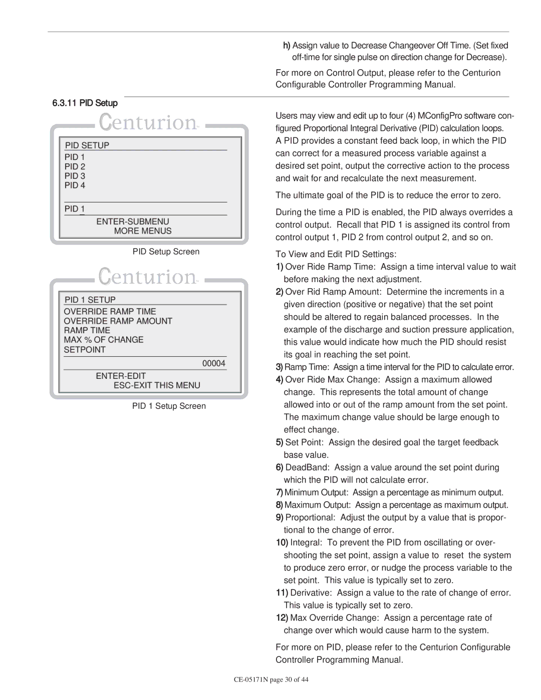
| PID Setup Screen |
| |
| C | TM |
|
|
|
| |
PID 1 SETUP |
|
| |
OVERRIDE RAMP TIME |
| ▼ | |
OVERRIDE RAMP AMOUNT |
|
| |
RAMP TIME
MAX % OF CHANGE
SETPOINT
___________________________________
| 00004 | ▼ |
___________________________________ | ||
▼▲ |
| |
|
| |
PID 1 Setup Screen
h)Assign value to Decrease Changeover Off Time. (Set fixed
For more on Control Output, please refer to the Centurion Configurable Controller Programming Manual.
Users may view and edit up to four (4) MConfigPro software con- figured Proportional Integral Derivative (PID) calculation loops.
A PID provides a constant feed back loop, in which the PID can correct for a measured process variable against a desired set point, output the corrective action to the process and wait for and recalculate the next measurement.
The ultimate goal of the PID is to reduce the error to zero.
During the time a PID is enabled, the PID always overrides a control output. Recall that PID 1 is assigned its control from control output 1, PID 2 from control output 2, and so on.
To View and Edit PID Settings:
1)Over Ride Ramp Time: Assign a time interval value to wait before making the next adjustment.
2)Over Rid Ramp Amount: Determine the increments in a given direction (positive or negative) that the set point should be altered to regain balanced processes. In the example of the discharge and suction pressure application, this value would indicate how much the PID should resist its goal in reaching the set point.
3)Ramp Time: Assign a time interval for the PID to calculate error.
4)Over Ride Max Change: Assign a maximum allowed change. This represents the total amount of change allowed into or out of the ramp amount from the set point. The maximum change value should be large enough to effect change.
5)Set Point: Assign the desired
6)DeadBand: Assign a value around the set point during which the PID will not calculate error.
7)Minimum Output: Assign a percentage as minimum output.
8)Maximum Output: Assign a percentage as maximum output.
9)Proportional: Adjust the output by a value that is propor- tional to the change of error.
10)Integral: To prevent the PID from oscillating or over- shooting the set point, assign a value to “reset” the system to produce zero error, or nudge the process variable to the set point. This value is typically set to zero.
11)Derivative: Assign a value to the rate of change of error. This value is typically set to zero.
12)Max Override Change: Assign a percentage rate of change over which would cause harm to the system.
For more on PID, please refer to the Centurion Configurable Controller Programming Manual.