N-Tron 710FX2 user manual Standard N-Link Configuration Example

Models: 710FX2

1 159
Download 159 pages 1.36 Kb
Page 95
Image 95

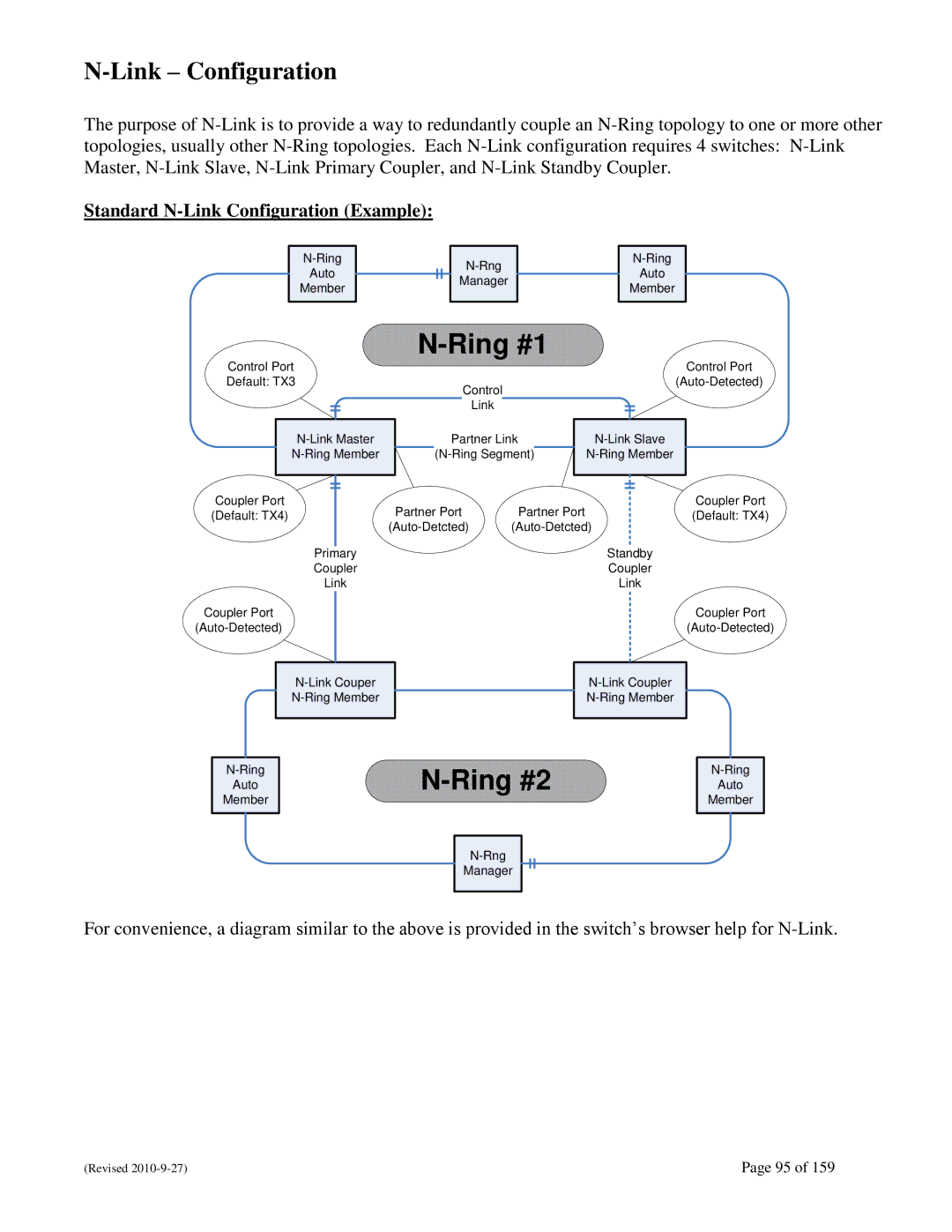
N-Link – Configuration

The purpose of N-Link is to provide a way to redundantly couple an N-Ring topology to one or more other topologies, usually other N-Ring topologies. Each N-Link configuration requires 4 switches: N-Link Master, N-Link Slave, N-Link Primary Coupler, and N-Link Standby Coupler.

Standard N-Link Configuration (Example):

N-Ring

Auto

Member

N-Rng

Manager

N-Ring

Auto

Member

N-Ring #1

Control Port

Default: TX3

N-Link Master

N-Ring Member

Control

Link

Partner Link

(N-Ring Segment)

Control Port

(Auto-Detected)

N-Link Slave

N-Ring Member

Coupler Port

Partner Port

Partner Port

Coupler Port

(Default: TX4)

(Default: TX4)

(Auto-Detcted)

(Auto-Detcted)


Primary


Standby


Coupler


Coupler


Link


Link

Coupler Port


Coupler Port

(Auto-Detected)


(Auto-Detected)

N-Link Couper N-Ring Member

N-Link Coupler N-Ring Member

N-Ring

Auto

Member

N-Ring #2

N-Rng

Manager

N-Ring

Auto

Member

For convenience, a diagram similar to the above is provided in the switch‘s browser help for N-Link.

(Revised 2010-9-27)

Page 95 of 159

Page 95
Image 95
N-Tron 710FX2 user manual Standard N-Link Configuration Example