16
VERTICAL VENTING INSTALLATION
1.Move the fireplace into position.
2.Fasten the roof support to the roof using the screws provided. FIGURE 21. The roof support is optional. In this case the venting is to be adequately supported using ei- ther an alternate method suitable to the authority having jurisdiction or the optional roof support.
3.Apply high temperature sealant to the outer edge of the inner sleeve of the air terminal. Slip a 5" diameter coupler a minimum of 2" over the sleeve and secure using 3 screws.
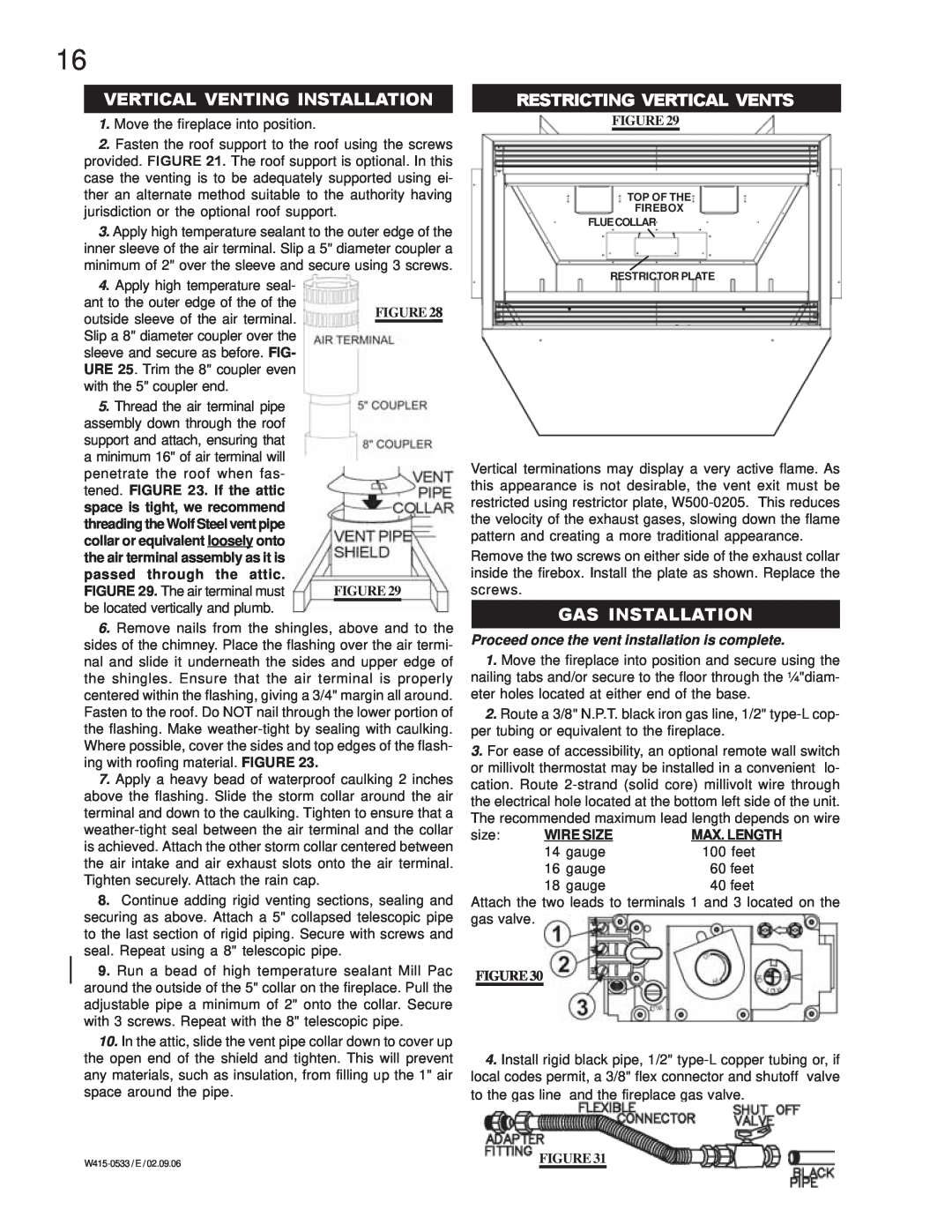
RESTRICTING VERTICAL VENTS
FIGURE 29
TOP OF THE
FIREBOX
FLUECOLLAR
RESTRICTOR PLATE
4. Apply high temperature seal- ant to the outer edge of the of the outside sleeve of the air terminal. Slip a 8" diameter coupler over the sleeve and secure as before. FIG- URE 25. Trim the 8" coupler even with the 5" coupler end.
5. Thread the air terminal pipe assembly down through the roof support and attach, ensuring that a minimum 16" of air terminal will penetrate the roof when fas- tened. FIGURE 23. If the attic space is tight, we recommend threading the Wolf Steel vent pipe collar or equivalent loosely onto the air terminal assembly as it is passed through the attic. FIGURE 29. The air terminal must be located vertically and plumb.
FIGURE 28
FIGURE 29
Vertical terminations may display a very active flame. As this appearance is not desirable, the vent exit must be restricted using restrictor plate,
Remove the two screws on either side of the exhaust collar inside the firebox. Install the plate as shown. Replace the screws.
GAS INSTALLATION
6.Remove nails from the shingles, above and to the sides of the chimney. Place the flashing over the air termi- nal and slide it underneath the sides and upper edge of the shingles. Ensure that the air terminal is properly centered within the flashing, giving a 3/4" margin all around. Fasten to the roof. Do NOT nail through the lower portion of the flashing. Make
7.Apply a heavy bead of waterproof caulking 2 inches above the flashing. Slide the storm collar around the air terminal and down to the caulking. Tighten to ensure that a
8.Continue adding rigid venting sections, sealing and securing as above. Attach a 5" collapsed telescopic pipe to the last section of rigid piping. Secure with screws and seal. Repeat using a 8" telescopic pipe.
9.Run a bead of high temperature sealant Mill Pac around the outside of the 5" collar on the fireplace. Pull the adjustable pipe a minimum of 2" onto the collar. Secure with 3 screws. Repeat with the 8" telescopic pipe.
10.In the attic, slide the vent pipe collar down to cover up the open end of the shield and tighten. This will prevent any materials, such as insulation, from filling up the 1" air space around the pipe.
Proceed once the vent installation is complete.
1.Move the fireplace into position and secure using the nailing tabs and/or secure to the floor through the ¼"diam- eter holes located at either end of the base.
2.Route a 3/8" N.P.T. black iron gas line, 1/2"
3.For ease of accessibility, an optional remote wall switch or millivolt thermostat may be installed in a convenient lo- cation. Route
size: | WIRE SIZE | MAX. LENGTH | |
| 14 | gauge | 100 feet |
| 16 | gauge | 60 feet |
| 18 | gauge | 40 feet |
Attach the two leads to terminals 1 and 3 located on the gas valve.
FIGURE 30
4.Install rigid black pipe, 1/2"
FIGURE 31 | |
|