DS90C3202
Two-Wire Serial Communication Interface Description
The DS90C3202 operates as a slave on the Serial Bus, so the S2CLK line is an input (no clock is generated by the DS90C3202) and the S2DAT line is
A zero in front of the register address is required. For ex- ample, to access register 0x0Fh, “0F” is the correct way of accessing the register.
COMMUNICATING WITH THE DS90C3202 CONTROL REGISTERS
There are 32 data registers (one byte each) in the DS90C3202, and can be accessed through 32 addresses. All registers are predefined as read only or read and write. The DS90C3202 slave state machine does not require an internal clock and it supports only byte read and write. Page mode is not supported. The 7bit binary address is 0111110 All seven bits are hardwired internally.
Reading the DS90C3202 can take place either of three ways:
1.If the location latched in the data register addresses is correct, then the read can simply consist of a slave address byte, followed by retrieving the data byte.
2.If the data register address needs to be set, then a slave address byte, data register address will be sent first, then the master will repeat start, send the slave address byte and data byte to accomplish a read.
3.When performing continuous read operations, another write (or read) instruction in between reads needs to be completed in order for the
The data byte has the most significant bit first. At the end of a read, the DS90C3202 can accept either Acknowledge or No Acknowledge from the Master (No Acknowledge is typi- cally used as a signal for the slave that the Master has read its last byte).
20147119
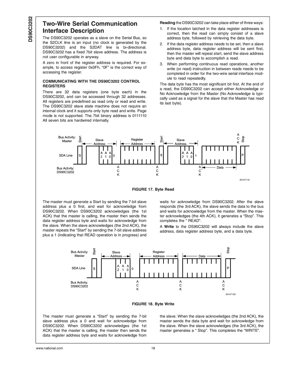
FIGURE 17. Byte Read
The master must generate a Start by sending the
waits for acknowledge from DS90C3202. After the slave responds (the 3rd ACK), the slave sends the data to the bus and waits for acknowledge from the master. When the mas- ter acknowledges (the 4th ACK), it generates a “Stop”. This completes the “ READ”.
A Write to the DS90C3202 will always include the slave address, data register address byte, and a data byte.
| 20147120 |
FIGURE 18. Byte Write | |
The master must generate a “Start” by sending the | the slave. When the slave acknowledges (the 2nd ACK), the |
slave address plus a 0 and wait for acknowledge from | master sends the data byte and wait for acknowledge from |
DS90C3202. When DS90C3202 acknowledges (the 1st | the slave. When the slave acknowledges (the 3rd ACK), the |
ACK) that the master is calling, the master then sends the | master generates a “ Stop”. This completes the “WRITE”. |
data register address byte and waits for acknowledge from |
|
www.national.com | 18 |