DS90C3202
DS90C3202 | (Continued) | |||||
|
|
|
|
|
|
|
Address | R/W | RESET | Bit # | Description |
| Default Value |
|
|
|
|
|
|
|
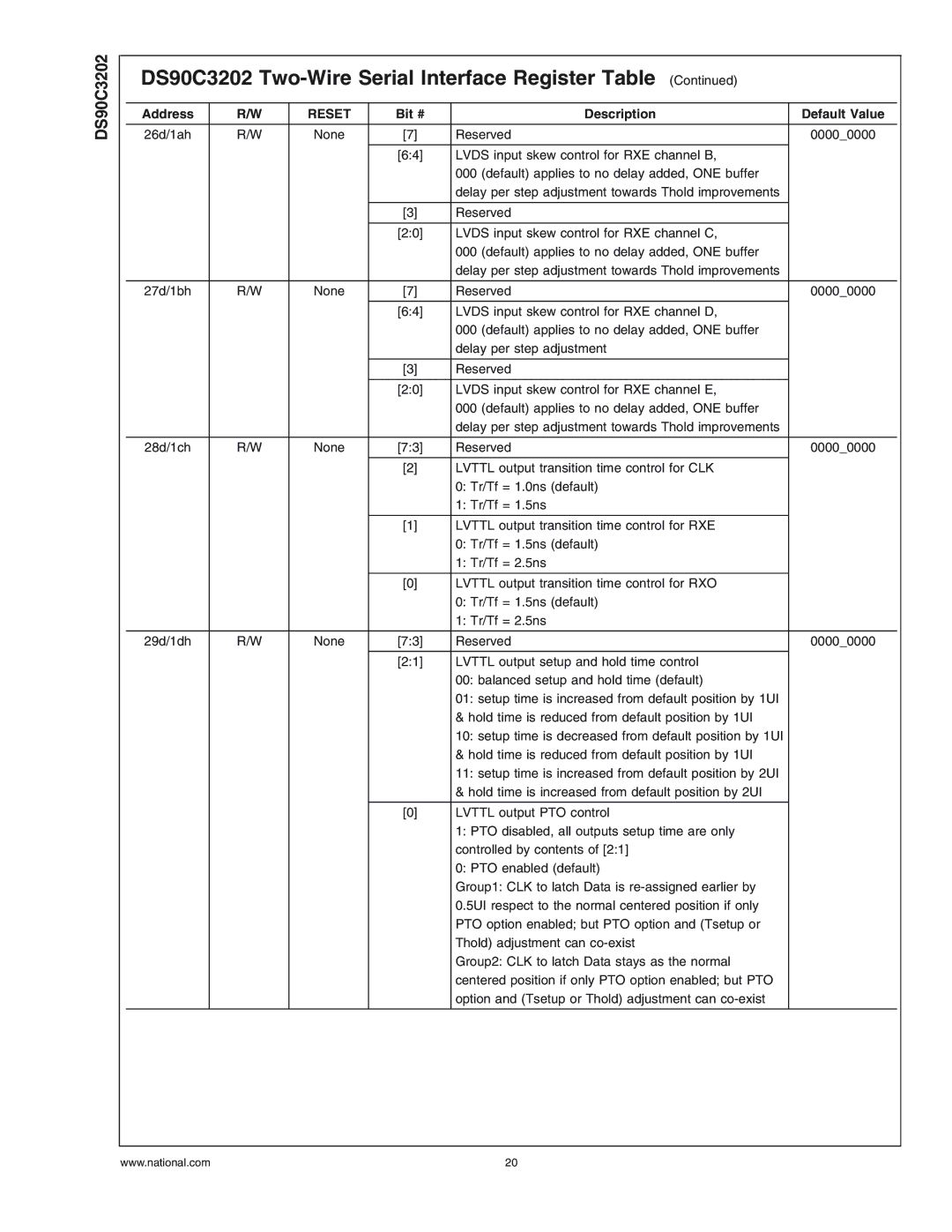
26d/1ah | R/W | None | [7] | Reserved |
| 0000_0000 |
|
|
|
|
|
| |
|
|
| [6:4] | LVDS input skew control for RXE channel B, |
| |
|
|
|
| 000 (default) applies to no delay added, ONE buffer |
| |
|
|
|
| delay per step adjustment towards Thold improvements |
| |
|
|
|
|
|
|
|
|
|
| [3] | Reserved |
|
|
|
|
|
|
|
| |
|
|
| [2:0] | LVDS input skew control for RXE channel C, |
| |
|
|
|
| 000 (default) applies to no delay added, ONE buffer |
| |
|
|
|
| delay per step adjustment towards Thold improvements |
| |
|
|
|
|
|
|
|
27d/1bh | R/W | None | [7] | Reserved |
| 0000_0000 |
|
|
|
|
|
| |
|
|
| [6:4] | LVDS input skew control for RXE channel D, |
| |
|
|
|
| 000 (default) applies to no delay added, ONE buffer |
| |
|
|
|
| delay per step adjustment |
|
|
|
|
|
|
|
|
|
|
|
| [3] | Reserved |
|
|
|
|
|
|
|
| |
|
|
| [2:0] | LVDS input skew control for RXE channel E, |
| |
|
|
|
| 000 (default) applies to no delay added, ONE buffer |
| |
|
|
|
| delay per step adjustment towards Thold improvements |
| |
|
|
|
|
|
|
|
28d/1ch | R/W | None | [7:3] | Reserved |
| 0000_0000 |
|
|
|
|
|
| |
|
|
| [2] | LVTTL output transition time control for CLK |
| |
|
|
|
| 0: Tr/Tf = 1.0ns (default) |
|
|
|
|
|
| 1: Tr/Tf = 1.5ns |
|
|
|
|
|
|
|
| |
|
|
| [1] | LVTTL output transition time control for RXE |
| |
|
|
|
| 0: Tr/Tf = 1.5ns (default) |
|
|
|
|
|
| 1: Tr/Tf = 2.5ns |
|
|
|
|
|
|
|
| |
|
|
| [0] | LVTTL output transition time control for RXO |
| |
|
|
|
| 0: Tr/Tf = 1.5ns (default) |
|
|
|
|
|
| 1: Tr/Tf = 2.5ns |
|
|
|
|
|
|
|
|
|
29d/1dh | R/W | None | [7:3] | Reserved |
| 0000_0000 |
|
|
|
|
|
| |
|
|
| [2:1] | LVTTL output setup and hold time control |
| |
|
|
|
| 00: balanced setup and hold time (default) |
| |
|
|
|
| 01: setup time is increased from default position by 1UI |
| |
|
|
|
| & hold time is reduced from default position by 1UI |
| |
|
|
|
| 10: setup time is decreased from default position by 1UI |
| |
|
|
|
| & hold time is reduced from default position by 1UI |
| |
|
|
|
| 11: setup time is increased from default position by 2UI |
| |
|
|
|
| & hold time is increased from default position by 2UI |
| |
|
|
|
|
|
|
|
|
|
| [0] | LVTTL output PTO control |
|
|
|
|
|
| 1: PTO disabled, all outputs setup time are only |
| |
|
|
|
| controlled by contents of [2:1] |
|
|
|
|
|
| 0: PTO enabled (default) |
|
|
|
|
|
| Group1: CLK to latch Data is |
| |
|
|
|
| 0.5UI respect to the normal centered position if only |
| |
|
|
|
| PTO option enabled; but PTO option and (Tsetup or |
| |
|
|
|
| Thold) adjustment can |
|
|
|
|
|
| Group2: CLK to latch Data stays as the normal |
| |
|
|
|
| centered position if only PTO option enabled; but PTO |
| |
|
|
|
| option and (Tsetup or Thold) adjustment can |
| |
|
|
|
|
|
|
|
www.national.com | 20 |
