Secondary alarm wiring option (FISH 4433 only)
Green Wire: Use this to connect a secondary alarm indicator such as a flashing light or external beeper with a
If the external beeper or light requires more than 200 mA total, fit a relay. Consult your Navman dealer for more advice.
Fuel kit wiring (FISH 4433 only)
See the Fuel Kit Installation Guide for information about the fuel transducer cable.
Wire the power cable for Auto power (as described in this section) to make sure the fuel counter starts as soon as the engine starts.
For twin engine installation, a
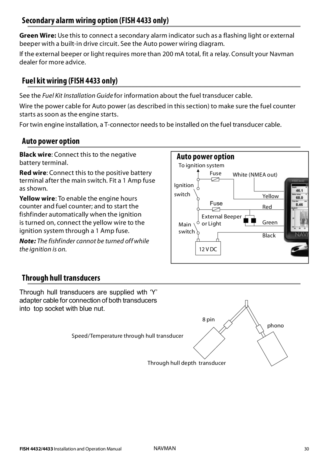
Auto power option
Black wire: Connect this to the negative | Auto power option |
| |||||||||||||||
battery terminal. | To ignition system |
|
|
|
|
|
|
| |||||||||
|
|
|
|
|
|
|
| ||||||||||
Red wire: Connect this to the positive battery |
|
|
|
| Fuse | White (NMEA out) |
| ||||||||||
|
|
|
| ||||||||||||||
terminal after the main switch. Fit a 1 Amp fuse | Ignition |
|
|
|
|
|
|
|
|
|
|
|
|
|
| ||
|
|
|
|
|
|
|
|
|
|
|
|
|
| ||||
as shown. |
|
|
|
|
|
|
|
|
|
|
|
|
|
| |||
switch |
|
|
|
|
|
|
|
|
|
|
|
|
|
| |||
Yellow wire: To enable the engine hours |
|
|
|
|
|
|
|
|
|
|
|
| Yellow |
| |||
counter and fuel counter; and to start the |
|
|
|
| Fuse |
|
|
|
|
| Red |
| |||||
|
|
|
|
|
|
|
|
|
|
|
|
|
|
|
| ||
fishfinder automatically when the ignition |
|
|
|
| External Beeper |
|
|
|
|
|
| ||||||
is turned on, connect the yellow wire to the | Main |
| or Light |
|
|
|
|
| Green |
| |||||||
ignition system through a 1 Amp fuse. | switch |
|
|
|
|
|
|
|
|
|
|
|
|
|
| ||
Note: The fishfinder cannot be turned off while |
|
|
|
|
|
|
|
|
|
|
|
|
|
|
| Black |
|
|
|
|
|
|
|
|
|
|
|
|
|
|
|
|
|
| |
|
|
|
|
|
|
|
|
|
|
|
|
|
|
|
|
| |
the ignition is on. |
|
|
| 12 V DC |
|
|
|
|
|
|
|
| |||||
|
|
|
|
|
|
|
|
|
|
|
|
|
|
|
|
|
|
|
|
|
|
|
|
|
|
|
|
|
|
|
|
|
|
|
|
Through hull transducers
Through hull transducers are supplied wth ‘Y’ adapter cable for connection of both transducers into top socket with blue nut.
8 pin
phono
Speed/Temperature through hull transducer
Through hull depth transducer
FISH 4432/4433 Installation and Operation Manual | NAVMAN | 30 |