6 Installation and Maintenance
Correct installation is critical to the performance of the FISH 4432/4433. There are two components to install, the display unit and
the transducer. It is vital to read the entire installation section of this manual before attempting to install the components.
Wiring Options
The power/data cable contains 5 wires:
Wire | Function |
Black | Ground (power negative) |
White* | NMEA out |
Red | Positive power in, 12 V DC |
Yellow | Auto power in (connect to red |
| wire. Positive power in, to enable |
| Auto power). |
Green* | External beeper or light out, |
| switched to ground, 30 V DC 200 |
| mA maximum. |
Note: The cable shield is connected to Pin 1 (black wire) and does not need to be grounded.
* Denotes FISH 4433 only.
Warning
1 Amp fuses must be positioned where shown in the wiring diagrams.
Six wiring options are described in this section:
•Basic wiring. This does not start the fishfinder automatically when the boat ignition is switched on and it disables the engine hours counter.
•Auto power wiring. This must be used for the engine hours and fuel computer options.
•Secondary Alarm wiring
•NMEA wiring
•Single engine fuel wiring
•Twin engine fuel wiring
Note: If a wire colour is not specifically mentioned, it is not used in that wiring option.
Section
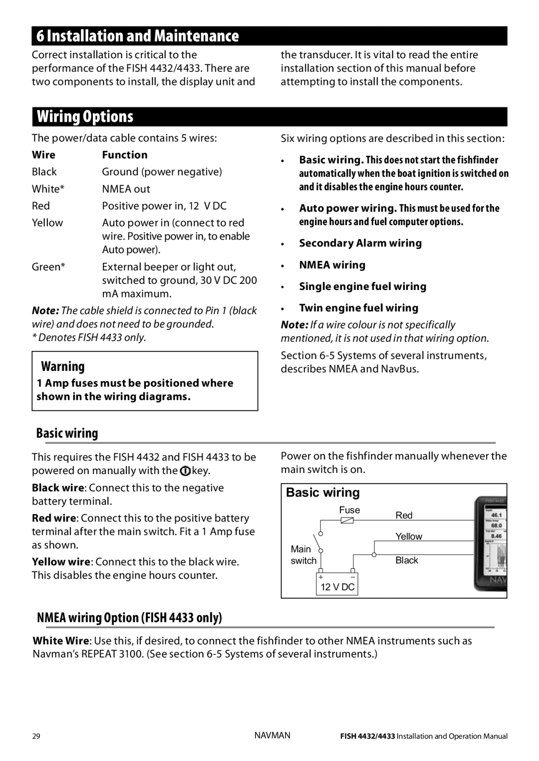
Basic wiring
This requires the FISH 4432 and FISH 4433 to be powered on manually with the ![]() key.
key.
Black wire: Connect this to the negative battery terminal.
Red wire: Connect this to the positive battery terminal after the main switch. Fit a 1 Amp fuse as shown.
Yellow wire: Connect this to the black wire. This disables the engine hours counter.
Power on the fishfinder manually whenever the main switch is on.
Basic wiring
Fuse
Red
Main | Yellow | |
Black | ||
switch | ||
| 12 V DC |
NMEA wiring Option (FISH 4433 only)
White Wire: Use this, if desired, to connect the fishfinder to other NMEA instruments such as Navman’s REPEAT 3100. (See section
29 | NAVMAN | FISH 4432/4433 Installation and Operation Manual |
