
120Mf, 5800 specifications
The NEC 5800 series is a line of highly regarded enterprise servers that have made a significant impact in the data center landscape. Known for their robustness, scalability, and efficient performance, these servers are designed to meet the growing needs of businesses across various sectors. The NEC 5800 series incorporates a range of cutting-edge technologies and features that cater to both high-performance computing and data-intensive applications.One of the standout features of the NEC 5800 is its modular design. This architecture allows organizations to customize their server configurations according to specific requirements, making it a versatile choice for a diverse range of workloads. The scalability provided by the NEC 5800 enables businesses to expand their operations easily, whether through adding additional resources or integrating new technologies as demands evolve.
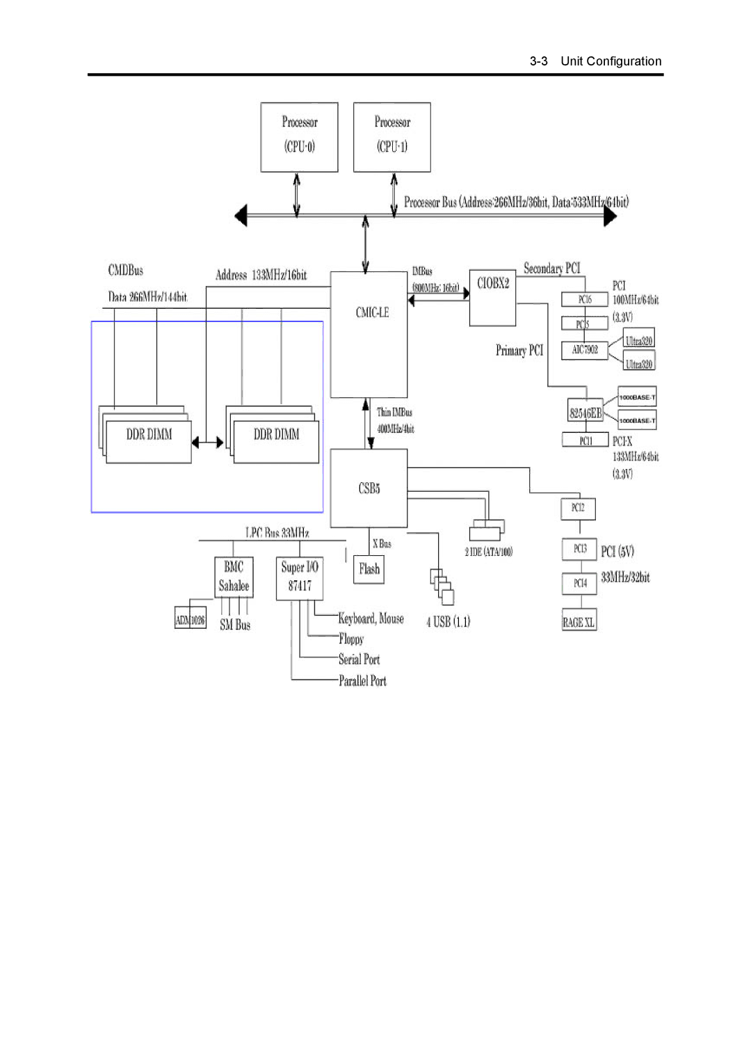
The NEC 5800 series utilizes advanced Intel Xeon processors, delivering exceptional computing power and multitasking capabilities. This ensures that mission-critical applications operate seamlessly, even under heavy workloads. Additionally, the integration of large memory capacities allows for efficient processing of big data analytics and virtualization, enabling businesses to harness the full potential of their data assets.
Another notable characteristic of the NEC 5800 series is its energy efficiency. With rising concerns about power consumption and operational costs, NEC has incorporated green technologies within their servers. The series features power-saving components and intelligent cooling systems that optimize energy usage, providing significant cost savings over time while minimizing environmental impact.
In terms of reliability, the NEC 5800 series comes equipped with a comprehensive set of features aimed at maintaining uptime and data integrity. This includes advanced RAID configurations, redundant power supplies, and hot-swappable components that allow for maintenance without downtime. Such features are critical for organizations that require continuous access to their applications and data.
Security is another essential aspect of the NEC 5800 series. It incorporates various security measures, including hardware-based authentication and encryption, to protect sensitive information. With the increasing number of cyber threats, these security features ensure that organizations can operate confidently without compromising their data integrity.
In conclusion, the NEC 5800 serves as a testament to NEC's commitment to delivering high-performance, reliable, and secure server solutions tailored to meet the demands of modern businesses. With its blend of scalability, energy efficiency, and robust security, it continues to be a preferred choice for enterprises aiming to leverage technology for growth and innovation.