FS518T.Manual.FINAL 5/19/00 12:55 PM Page 19
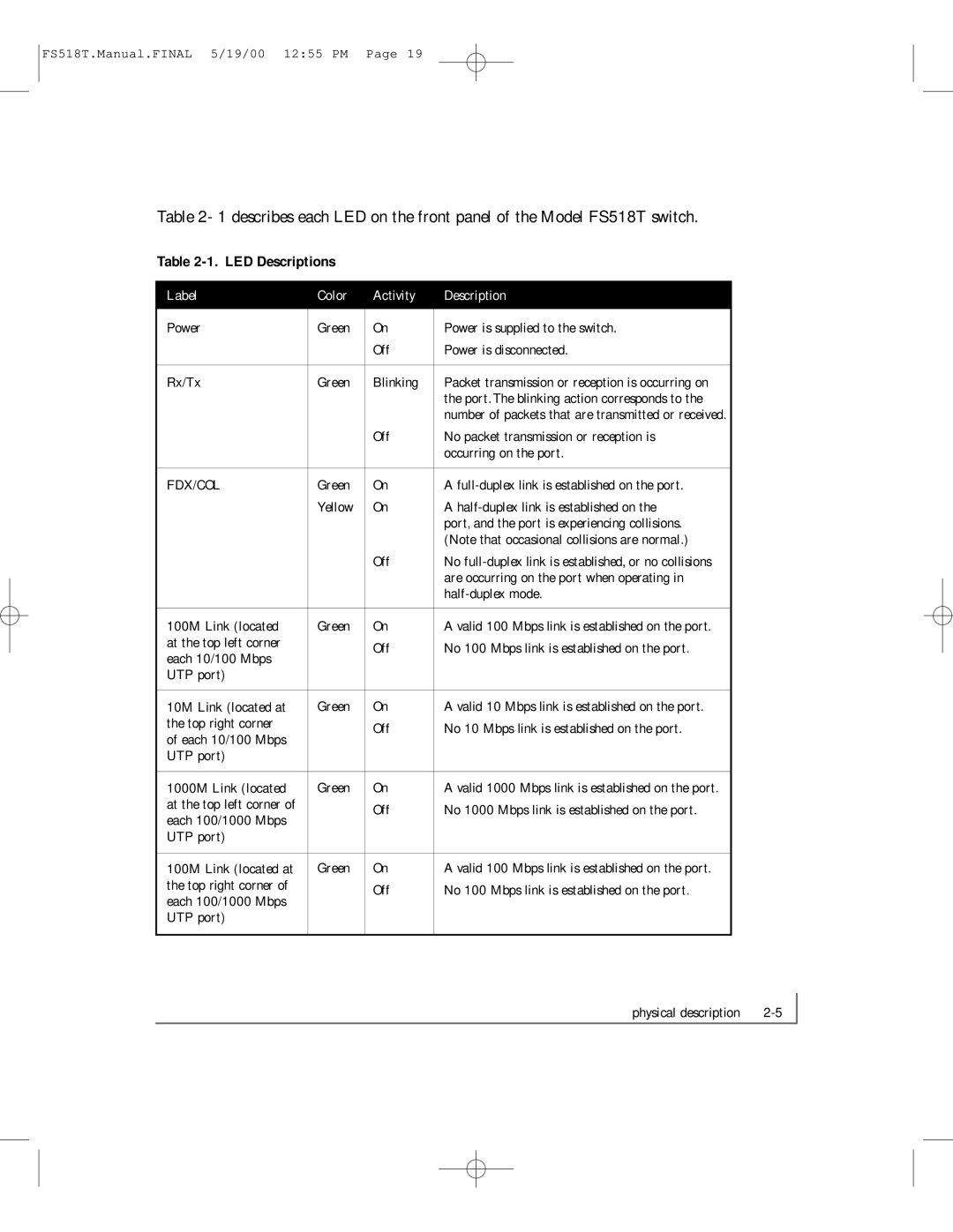
Table 2- 1 describes each LED on the front panel of the Model FS518T switch.
Table 2-1. LED Descriptions
Label | Color | Activity | Description |
|
|
|
|
Power | Green | On | Power is supplied to the switch. |
|
| Off | Power is disconnected. |
|
|
|
|
Rx/Tx | Green | Blinking | Packet transmission or reception is occurring on |
|
|
| the port. The blinking action corresponds to the |
|
|
| number of packets that are transmitted or received. |
|
| Off | No packet transmission or reception is |
|
|
| occurring on the port. |
|
|
|
|
FDX/COL | Green | On | A |
| Yellow | On | A |
|
|
| port, and the port is experiencing collisions. |
|
|
| (Note that occasional collisions are normal.) |
|
| Off | No |
|
|
| are occurring on the port when operating in |
|
|
| |
|
|
|
|
100M Link (located | Green | On | A valid 100 Mbps link is established on the port. |
at the top left corner |
| Off | No 100 Mbps link is established on the port. |
each 10/100 Mbps |
| ||
|
|
| |
UTP port) |
|
|
|
|
|
|
|
10M Link (located at | Green | On | A valid 10 Mbps link is established on the port. |
the top right corner |
| Off | No 10 Mbps link is established on the port. |
of each 10/100 Mbps |
| ||
|
|
| |
UTP port) |
|
|
|
|
|
|
|
1000M Link (located | Green | On | A valid 1000 Mbps link is established on the port. |
at the top left corner of |
| Off | No 1000 Mbps link is established on the port. |
each 100/1000 Mbps |
| ||
|
|
| |
UTP port) |
|
|
|
|
|
|
|
100M Link (located at | Green | On | A valid 100 Mbps link is established on the port. |
the top right corner of |
| Off | No 100 Mbps link is established on the port. |
each 100/1000 Mbps |
| ||
|
|
| |
UTP port) |
|
|
|
|
|
|
|
physical description |
