FS518T.Manual.FINAL 5/19/00 12:55 PM Page 15
CHAPTER 2: PHYSICAL DESCRIPTION
This chapter describes the hardware features of the NETGEAR Model FS518T Fast Ethernet Switch.
Front Panel
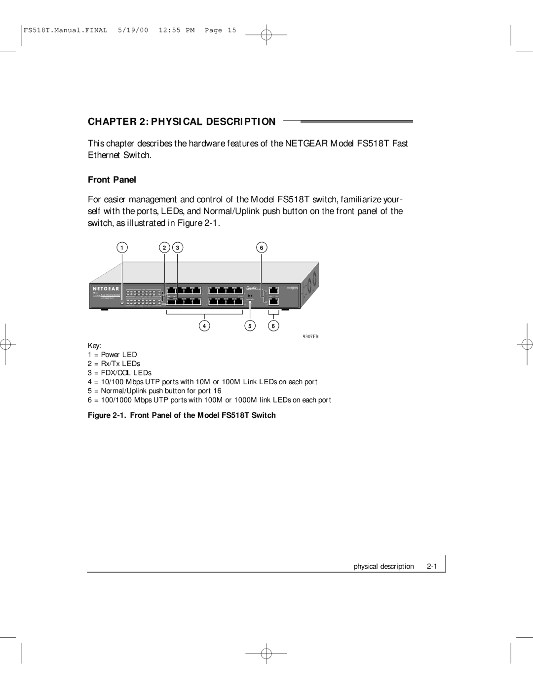
For easier management and control of the Model FS518T switch, familiarize your- self with the ports, LEDs, and Normal/Uplink push button on the front panel of the switch, as illustrated in Figure
1 | 2 | 3 | 6 |
|
|
|
|
|
|
|
|
|
|
|
|
|
| Activity |
|
|
|
|
|
|
| |
18PORT |
|
|
|
|
|
|
|
|
|
|
|
|
|
|
|
|
|
| ||||
1 |
| 2 | 3 | 4 | 5 |
| 6 | 7 | 8 | 17 | ||||||||||||
10/100Mbps Fast Ethernet Switch |
|
|
|
|
|
|
|
|
|
|
|
|
|
|
|
|
|
| ||||
| with Gigabit Ports |
|
|
|
|
|
|
| Green = FDX, Yellow = COL |
|
|
|
| |||||||||
|
|
|
|
|
|
|
|
|
| Activity |
|
|
|
|
|
|
| |||||
|
|
|
|
|
|
|
|
|
|
|
|
|
|
|
|
|
|
|
|
|
|
|
|
| Power | 9 |
| 10 | 11 | 12 | 13 |
| 14 | 15 | 16 | 18 | |||||||||
|
|
|
|
|
|
|
|
|
|
|
|
|
|
|
|
|
|
|
|
|
|
|
|
|
|
|
|
|
|
|
|
|
| Green = FDX, Yellow = COL |
|
|
|
| |||||||
|
|
|
|
|
|
|
|
|
|
|
|
|
|
|
|
|
|
|
|
|
|
|
1 ![]()
100M 10M
9 ![]()
45
12 13
![]() Switching
Switching
8
On = Link
Normal/Uplink
16
17 ![]()
![]()
1000M | 100M |
18 |
|
MODEL FS518T
4 | 5 | 6 |
9307FB
Key:
1 = Power LED
2 = Rx/Tx LEDs
3 = FDX/COL LEDs
4 = 10/100 Mbps UTP ports with 10M or 100M Link LEDs on each port 5 = Normal/Uplink push button for port 16
6 = 100/1000 Mbps UTP ports with 100M or 1000M link LEDs on each port
Figure 2-1. Front Panel of the Model FS518T Switch
physical description |