DETERMINING THE LOCATION FOR DV1000
Note: The installation must conform with local codes or, in the absence of local codes, with the National Fuel Gas Code, ANSI Z223.1/NFPA 54, or the Natural Gas and Propane Instal- lation Code, CSA B149.1.
This appliance may be installed in an aftermarket, permanently located, manufactured home (USA only) or mobile home, where not prohibited by local codes.
This appliance is only for use with the type of gas indicated on the rating plate. This appli- ance is not convertible for use with other gases, unless a certified kit is used.
Due to high temperatures, the appliance should be located out of traffic and away from fur- niture and draperies.
The appliance, when installed, must be electrically grounded in accordance with local codes or, or in the absence of local codes, with the National Electrical Code, ANSI/NFPA 70, or the Canadian Electrical Code CSA C22.1.
The Model DV1000 Direct Vent Fireplace must be vented using only Magnaflex
You must check the Vent Termination Clearance requirements from decks, windows, soffits, gas regulators, air supply inlets, and public walkways, etc. as shown in these instructions and speci- fied by local building codes (see figure 4, page 7). This gas appliance must be vented directly to the outside of the building. This gas appliance must not be connected to a chimney flue serving a separate
MINIMUM CLEARANCE TO COMBUSTIBLE MATERIAL FROM FIREPLACE AND VENT SURFACES:
Sides, Back, Bottom and Top of appliance (standoffs) | 0 inch | |
Recessed depth to back of front trim | 17 inches | |
Recessed depth to front of front trim | ||
Diameter of vent pipe | 2 | inches |
Top of appliance to ceiling | 54 | inches |
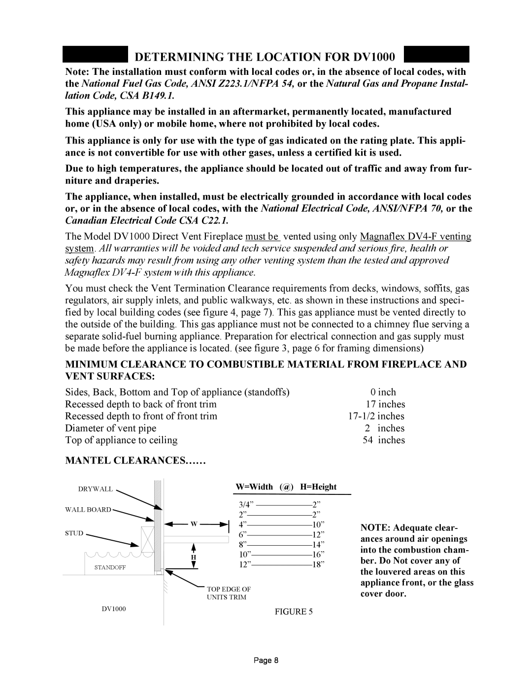
MANTEL CLEARANCES……
DRYWALL | W=Width (@) H=Height |
| |
WALL BOARD | 3/4” |
| |
| |||
| NOTE: Adequate clear- | ||
W | |||
|
| ||
STUD | ances around air openings | ||
| |||
| into the combustion cham- | ||
H | |||
ber. Do Not cover any of | |||
STANDOFF | |||
the louvered areas on this | |||
|
| ||
| TOP EDGE OF | appliance front, or the glass | |
| cover door. | ||
| UNITS TRIM | ||
DV1000 | FIGURE 5 |
|
Page 8