REMOVABLE INNER BOTTOM PAN ASSEMBLY
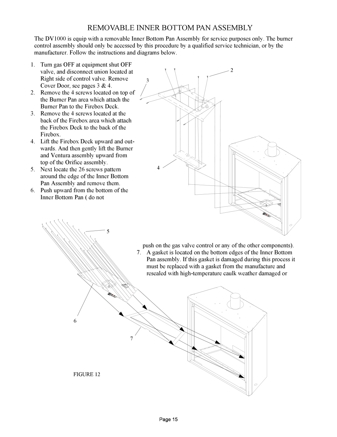
The DV1000 is equip with a removable Inner Bottom Pan Assembly for service purposes only. The burner control assembly should only be accessed by this procedure by a qualified service technician, or by the manufacturer. Follow the instructions and diagrams below.
1. | Turn gas OFF at equipment shut OFF | 2 |
| valve, and disconnect union located at | |
| Right side of control valve. Remove | 3 |
| Cover Door, see pages 3 & 4. |
|
2. | Remove the 4 screws located on top of |
|
| the Burner Pan area which attach the |
|
| Burner Pan to the Firebox Deck. |
|
3. | Remove the 4 screws located at the |
|
| back of the Firebox area which attach |
|
| the Firebox Deck to the back of the |
|
| Firebox. |
|
4. | Lift the Firebox Deck upward and out- |
|
| wards. And then gently lift the Burner |
|
| and Ventura assembly upward from |
|
| top of the Orifice assembly. | 4 |
5. | Next locate the 26 screws pattern | |
| around the edge of the Inner Bottom |
|
| Pan Assembly and remove them. |
|
6. | Push upward from the bottom of the |
|
| Inner Bottom Pan ( do not |
|
REV. DATE
DATE
![]()
![]() 5
5
push on the gas valve control or any of the other components).
7.A gasket is located on the bottom edges of the Inner Bottom Pan assembly. If this gasket is damaged during this process it must be replaced with a gasket from the manufacture and
resealed with
6
7
FIGURE 12
Page 15