∗The termination cap must be positioned so that the embossed arrow is pointed up.
∗Ensure that the venting system exits the structure through a sidewall or similar structure and does not terminate less than 12 inches (305mm) above the ground.
∗Ensure that the venting system is located above the snow line in geographical areas where snow accumulates.
PRE-INSTALLATION INFORMATION:
Items Required For Installation: |
|
|
| |
Tools |
|
| Building Supplies | |
Phillips Screwdriver | Measuring Tape | Framing Materials | ||
Hammer | Electric Drill and Bits |
|
|
|
Wall Finishing Materials |
| |||
Saw and/or saber saw | Pliers | Caulking Material (Noncombustible) | ||
Level | Square | Silicone Sealant (High Temp.) | ||
PIPE INSTALLATION:
Note: If you haven’t read pages 1 thru 9 completely “STOP”, and read them “NOW”.
1.Unpack vent components and check all items for shipping damage.
2.Locate Magnaflex
3.If Wall Straps are needed for your installation, determine the number of straps needed and ob- tain them before beginning the installation process.
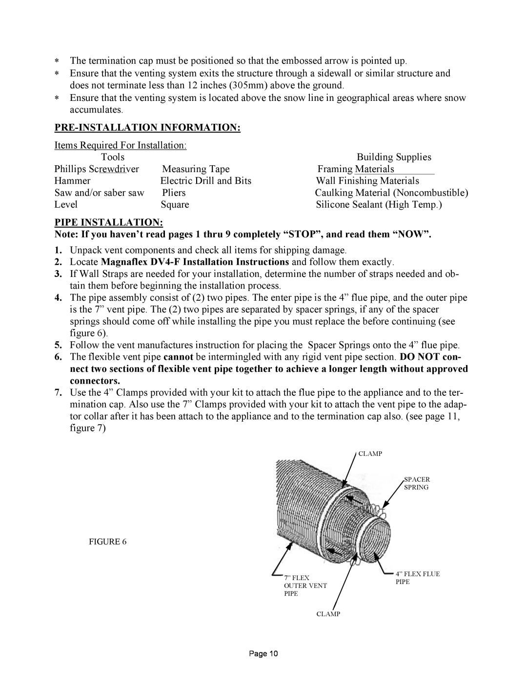
4.The pipe assembly consist of (2) two pipes. The enter pipe is the 4” flue pipe, and the outer pipe is the 7” vent pipe. The (2) two pipes are separated by spacer springs, if any of the spacer springs should come off while installing the pipe you must replace the before continuing (see figure 6).
5.Follow the vent manufactures instruction for placing the Spacer Springs onto the 4” flue pipe.
6.The flexible vent pipe cannot be intermingled with any rigid vent pipe section. DO NOT con- nect two sections of flexible vent pipe together to achieve a longer length without approved connectors.
7.Use the 4” Clamps provided with your kit to attach the flue pipe to the appliance and to the ter- mination cap. Also use the 7” Clamps provided with your kit to attach the vent pipe to the adap- tor collar after it has been attach to the appliance and to the termination cap also. (see page 11, figure 7)
CLAMP
SPACER
SPRING
FIGURE 6
|
|
|
|
|
|
|
|
|
|
|
|
|
|
|
|
|
|
|
|
|
|
|
|
|
|
|
|
|
|
|
|
|
|
|
|
|
|
|
|
|
|
|
|
|
| 7” FLEX |
|
|
|
|
|
| 4” FLEX FLUE | ||
|
|
|
|
|
|
|
|
|
| ||||
|
|
|
|
|
|
|
|
| |||||
|
|
|
|
|
|
|
|
|
| ||||
|
|
|
|
|
|
|
|
|
| PIPE | |||
|
|
|
| OUTER VENT |
|
|
|
|
|
| |||
|
|
|
|
|
|
|
|
|
| ||||
|
|
|
| PIPE |
|
|
|
|
|
| |||
|
|
|
|
|
|
|
|
|
| ||||
|
|
|
|
|
| ||||||||
|
|
|
|
|
|
|
|
|
|
|
|
| |
|
|
|
|
|
|
|
|
|
|
|
|
|
|
|
|
|
|
|
| CLAMP |
|
|
| ||||
Page 10