Preparing The Stove for Installation
1.Inspect the unit for any obvious physical damage.
2.Check the primary air draft controls to ensure that they slide freely.
3.Check the operation of the bypass damper control to ensure that it will open and close properly.
4.Remove any items from within the firebox. Spread the drop cloth on the floor behind the heater. Next, tilt the heater so that the back is on the drop cloth.
5.Using a tape measure, make a line down 3" from the front of the heater.
6.Open the corresponding box and obtain the pedestal. Place the pedestal against the bottom of the heater (angle side to heater) at the marked line. Center the pedestal left and right and mark screw locations on bottom through outer holes of pedestal mounting angles. Set pedestal aside and drill four 7/32" holes in heater bottom.
7.Obtain four 1/4" self tapping screws and secure the pedestal to the heater.
8.If you chose legs rather than a pedestal, open box, attach legs to
9.Reposition the heater to the upright position.
10.Obtain the chimney connector from your dealer. Position on top of stove at flue exit. Position the two “J” bolts in connector using lock washer and nuts provided. Lock in place.
CHIMNEY
Ceiling Exits (using Single Wall Pipe and UL 103 HT type chimney system listed with manufacturer in this section of manual)
The Model 80 is designed for connection to:
(1)Simpson Duravent (2) Security (3) Selkirk Metalbestos (4) Metal Fab (5) Air Jet, listed as 2100 degree pipe and parts.
Follow the chimney and chimney connector manu- facturer’s instructions and local building codes for installation through combustible walls or ceilings. This room heater must be converted to (1) a chim- ney complying with the requirements for Type HT chimneys in the Standard for Chimneys, Factory- Built, Residential, Type and Building Heating Appli- ance, UL 103, or (2) a code approved masonry chimney with a flue liner.
Caution: Certain installation types require the use of certain chimney types. Please follow these instructions exactly.
DETERMINING THE CHIMNEY LOCATION
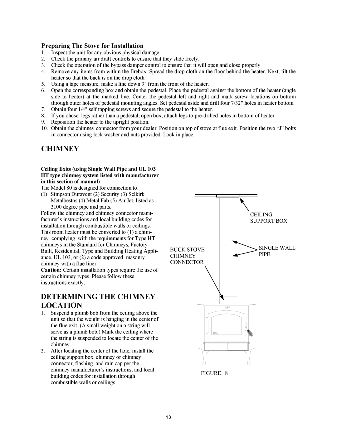
BUCK STOVE CHIMNEY CONNECTOR
CEILING
SUPPORT BOX
![]() SINGLE WALL PIPE
SINGLE WALL PIPE
1.Suspend a plumb bob from the ceiling above the unit so that the weight is hanging in the center of the flue exit. (A small weight on a string will serve as a plumb bob.) Mark the ceiling where the string is suspended to locate the center of the chimney.
2.After locating the center of the hole, install the ceiling support box, chimney or chimney connector, flashing, and rain cap per the chimney manufacturer’s instructions, and local building codes for installation through combustible walls or ceilings.
FIGURE 8
13