ENGLISH | USER MANUAL | |
|
| |
|
|
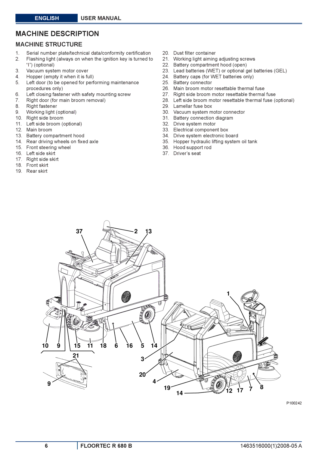
MACHINE DESCRIPTION
MACHINE STRUCTURE
1. | Serial number plate/technical data/conformity certification | 20. | Dust filter container |
2. | Flashing light (always on when the ignition key is turned to | 21. | Working light aiming adjusting screws |
| “I”) (optional) | 22. | Battery compartment hood (open) |
3. | Vacuum system motor cover | 23. | Lead batteries (WET) or optional gel batteries (GEL) |
4. | Hopper (empty it when it is full) | 24. | Battery caps (for WET batteries only) |
5. | Left door (to be opened for performing maintenance | 25. | Battery connector |
| procedures only) | 26. | Main broom motor resettable thermal fuse |
6. | Left closing fastener with safety mounting screw | 27. | Right side broom motor resettable thermal fuse |
7. | Right door (for main broom removal) | 28. | Left side broom motor resettable thermal fuse (optional) |
8. | Right fastener | 29. | Lamellar fuse box |
9. | Working light (optional) | 30. | Vacuum system motor connector |
10. | Right side broom | 31. | Battery connection diagram |
11. | Left side broom (optional) | 32. | Drive system motor |
12. | Main broom | 33. | Electrical component box |
13. | Battery compartment hood | 34. | Drive system electronic board |
14. | Rear driving wheels on fixed axle | 35. | Hopper hydraulic lifting system oil tank |
15. | Front steering wheel | 36. | Hood support rod |
16. | Left side skirt | 37. | Driver’s seat |
17.Right side skirt
18.Front skirt
19.Rear skirt
37 | 2 | 13 |
1
10 | 9 | 15 | 11 | 18 | 6 | 16 | 5 | 14 |
|
|
|
|
|
|
| 21 |
|
|
|
| 3 |
|
|
|
|
|
|
|
|
|
|
|
|
|
|
|
|
|
|
| |
|
|
|
|
|
|
| 20 | 4 |
|
|
|
|
|
9 |
|
|
|
|
|
|
|
|
|
|
| 8 | |
|
|
|
|
|
|
| 19 |
| 12 | 17 | 7 | ||
|
|
|
|
|
|
|
| 14 | |||||
|
|
|
|
|
|
|
|
|
|
|
|
|
P100242
6
FLOORTEC R 680 B |