ENGLISH | USER MANUAL | |
|
| |
|
|
SKIRT HEIGHT AND OPERATION CHECK
Preliminary procedure
1.Empty the hopper (as shown in the User Manual), because the weight of the waste inside the hopper can affect the skirt height check.
2.Drive the machine on a level floor that is suitable for checking the skirt height.
3.Engage the parking brake with the pedal (75) and the lever (68).
4.Turn the ignition key (67) to “0”.
Side skirt check
5.Release the fasteners (8 and 6), then open the right and left door (7 and 5).
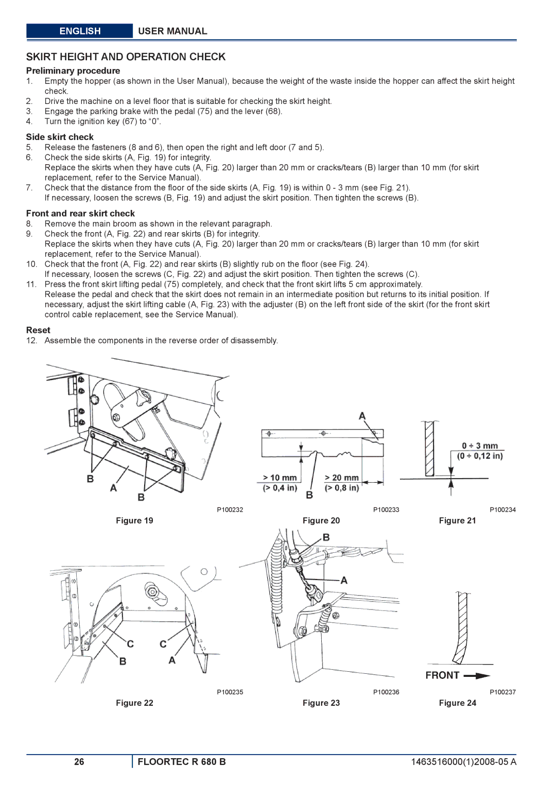
6.Check the side skirts (A, Fig. 19) for integrity.
Replace the skirts when they have cuts (A, Fig. 20) larger than 20 mm or cracks/tears (B) larger than 10 mm (for skirt replacement, refer to the Service Manual).
7.Check that the distance from the floor of the side skirts (A, Fig. 19) is within 0 - 3 mm (see Fig. 21). If necessary, loosen the screws (B, Fig. 19) and adjust the skirt position. Then tighten the screws (B).
Front and rear skirt check
8.Remove the main broom as shown in the relevant paragraph.
9.Check the front (A, Fig. 22) and rear skirts (B) for integrity.
Replace the skirts when they have cuts (A, Fig. 20) larger than 20 mm or cracks/tears (B) larger than 10 mm (for skirt replacement, refer to the Service Manual).
10.Check that the front (A, Fig. 22) and rear skirts (B) slightly rub on the floor (see Fig. 24).
If necessary, loosen the screws (C, Fig. 22) and adjust the skirt position. Then tighten the screws (C).
11.Press the front skirt lifting pedal (75) completely, and check that the front skirt lifts 5 cm approximately.
Release the pedal and check that the skirt does not remain in an intermediate position but returns to its initial position. If necessary, adjust the skirt lifting cable (A, Fig. 23) with the adjuster (B) on the left front side of the skirt (for the front skirt control cable replacement, see the Service Manual).
Reset
12. Assemble the components in the reverse order of disassembly.
P100232 | P100233 | P100234 |
Figure 19 | Figure 20 | Figure 21 |
P100235 | P100236 | P100237 |
Figure 22 | Figure 23 | Figure 24 |
26
FLOORTEC R 680 B |