Déclaration de conformité
Konformitätserklärung
Conformity certificate
Conformiteitsverklaring
19 2 17 15 16 4 5
14 13 12 11 3 10 9
18 8 7 20
3301481112005-07A
BETRIEBSANLEITUNG
ALLGEMEINE ANWEISUNGEN
EINLEITUNG
BETRIEBSANLEITUNG
VORBEDINGUNG
VERANTWORTLICHKEIT DES BEDIENERS
TERMINOLOGIEN UND IHRE BEDEUTUNG
SICHERHEITSVORSCHRIFTEN
Gefahrenbereiche
WARNZEICHEN
TRANSPORT, VERLAGERUNG, INSTALLATION
ABLANDEN UND VERLAGERN
Siehe Abb. C
TECHNISCHE EIGENSCHAFTEN
INSTALLATION
VERPACKUNG
ALLGEMEINE PRÜFUNGEN
SR 1450 B Siehe Abb. F
MASCHINENBESCHREIBUNG
Beschreibung der Maschine ohne Dach Siehe Abb. G
Beschreibung der Maschine mit Dach Siehe Abb. H
TECHNISCHE DATEN
SICHERHEITSSYSTEME
Instrumentenbrett
Hydraulische Anlage
GERÄUSCHPEGEL
UMGEBUNGSWERTE
SR 1450 B
Betrieb
STEUERUNGEN UND INSTRUMENTE
ANWENDUNG
SR 1450 D Siehe Abb. l
SR 1450 B Siehe Abb. J
GEBRAUCH DER MASCHINE
GEBRAUCHSANWEISUNGEN
Anlassen SR 1450 D
Ausschalten SR 1450 D
BETRIEBSANLEITUNG
MASCHINENABSTELLEN
Kehrgutsammeln SR 1450 B
BETRIEBSANLEITUNG
STÖRUNGEN UND ABHILFEN
STÖRUNGEN UND ABHILFEN
3301481112005-07A
BETRIEBSANLEITUNG
3301481112005-07A
Übermäßige Erwärmung des Motors SR 1450 B
BETRIEBSANLEITUNG
WARTUNGSTABELLE
REINIGUNG UND WARTUNG
REINIGUNG
PLANMÄSSIGE WARTUNG
3301481112005-07A
Gleichstrom-FahrmotorSR 1450 B
BETRIEBSANLEITUNG
Batterie SR 1450 D
PLANMÄSSIGE PRÜFUNGEN
Reifendruck
Ölstand
Einstellung der Feststellbremse
AUSSERORDENTLICHE WARTUNG
Ersetzung des Luftfilters SR 1450 D
Ersetzung des Hydraulikölfilters der Zahnradpumpe
SR 1450 B Betriebsnormen
BETRIEBSBATTERIE
Anwendung
Ladung
ABBAU
ABBAU, ENTSORGUNG
ENTSORGUNG
Abbau der Hydraulikanlagen
POSITION DER SICHERUNGEN
PLÄNE
SCHALTPLÄNE
SR 1450 D Siehe Abb. AG
HYDRAULIKPLAN
ZUBEHÖR UND SONDERAUSSTATTUNG
DRITTER SEITENBESEN
SR 1450 D Siehe Abb. AJ
TRANSPORT, MANUTENTION, INSTALLATION
MANUEL DUTILISATION
AVERTISSEMENTS GENERAUX
INTRODUCTION
AVANT-PROPOS
IDENTIFICATION DE LA MACHINE
TERMINOLOGIE ET SIGNIFICATION
PRECAUTIONS POUR LA SECURITE DES OPERATEURS
RESPONSABILITE DE LOPERATEUR
Zones dangereuses
SIGNAUX DATTENTION
TRANSPORT, MANUTENTION, INSTALLATION
DECHARGEMENT ET MANUTENTION
Voir Fig. C
EMBALLAGES
CARACTERISTIQUES TECHNIQUES
CONTROLES GENERAUX
UTILISATION PREVUE
SR 1450 B Voir Fig. F
DESCRIPTION DE LA MACHINE
Châssis
Conteneur déchets
DONNEES TECHNIQUES PRINCIPALES
SYSTEMES DE SECURITE
Tableau de bord
Système hydraulique
NIVEAU DE BRUIT
VALEURS ENVIRONNEMENTALES
Travail
Stockage
Commandes par leviers
COMMANDES ET INSTRUMENTS
UTILISATION
SR 1450 D Voir Fig.
UTILISATION DE LA MACHINE
INSTRUCTIONS POUR LUTILISATION
Démarrage SR 1450 D
Arrêt SR 1450 D
MANUEL DUTILISATION
ARRET DE LA MACHINE
Ramassage des déchets SR 1450 B
MANUEL DUTILISATION
PROBLEMES ET REMEDES
PROBLEMES ET REMEDES
Le fusible du secoueur grille
MANUEL DUTILISATION
PROBLEME
Réchauffement excessif du moteur SR 1450 B
MANUEL DUTILISATION
CAUSE
TABLEAU DENTRETIEN
NETTOYAGE ET ENTRETIEN
NETTOYAGE
ENTRETIEN PERIODIQUE
MANUEL DUTILISATION
Moteur à courant continu de traction SR 1450 B
Pression pneus
CONTROLES PERIODIQUES
Niveaux de lhuile
Niveau du liquide de réfroidissement SR 1450 D
Remplacement des joints latéraux droits
Remplacement du filtre à air SR 1450 D
Remplacement des joints latéraux gauches
Remplacement de la brosse centrale
SR 1450 B Normes de services
BATTERIE DE SERVICE
Utilisation
Charge
DEMANTELEMENT
DEMANTELEMENT, ECOULEMENT
ECOULEMENT
Démantèlement des circuits hydrauliques
SCHEMAS ELECTRIQUES
SCHEMAS
POSITION FUSIBLES
SR 1450 D Voir Fig. AG
SCHEMA HYDRAULIQUE
ACCESSOIRES ET OPTIONS
TROISIEME BROSSE
SR 1450 D Voir fig. AJ
USER MANUAL
USER MANUAL
GENERAL WARNINGS
FOREWORD
MACHINE IDENTIFICATION
DEFINITIONS
OPERATORS SAFETY PRECAUTIONS
OPERATORS RESPONSIBILITY
Danger zones
WARNING SIGNS
TRANSPORTATION, HANDLING, INSTALLATION
DISCHARGE AND HANDLING
See Fig. C
PACKING
TECHNICAL DATA
GENERAL CHECKS
MACHINE LAYOUT
SR 1450 B See Fig. F
MACHINE DESCRIPTION
Description of the machine with roof See Fig. H
Frame
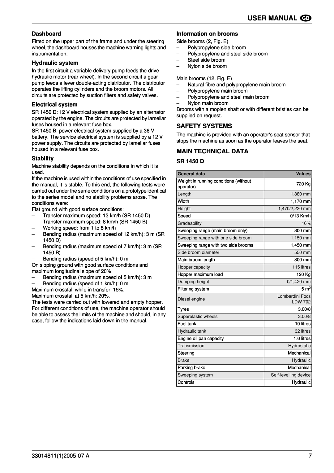
MAIN TECHNICAL DATA
SAFETY SYSTEMS
Dashboard
Hydraulic system
NOISE LEVEL
ENVIRONMENTAL CONDITIONS
Working
Storage
SR 1450 D See Fig.
CONTROLS AND INSTRUMENTS
SR 1450 B See Fig. J
Lever controls
MACHINE USE
INSTRUCTIONS FOR USE
Start SR 1450 D
Stop SR 1450 D
USER MANUAL
MACHINE STOP
Waste collection SR 1450 B
PROBLEMS AND REMEDIES
PROBLEMS AND REMEDIES
Blown filter shaker fuse
PROBLEM
SR 1450 B motor overheating SR 1450 B
CAUSE
REMEDY
MAINTENANCE TABLE
CLEANING AND MAINTENANCE
CLEANING
PERIODICAL MAINTENANCE
USER MANUAL
Drive direct current motor SR 1450 B
Skirt closing adjustment
Battery SR 1450 D
PERIODICAL CHECKS
Tyre pressure
Parking brake adjustment
EXTRAORDINARY MAINTENANCE
Engine air cleaner replacement SR 1450 D
Gear pump hydraulic oil filter replacement
SR 1450 B Service instructions
ACCESSORY BATTERY
Maintenance
Overcharge
DISMANTLING
DISMANTLING, DISPOSAL
DISPOSAL
Hydraulic system dismantling
WIRING DIAGRAMS
DIAGRAMS
FUSE POSITIONS
SR 1450 D See Fig. AG
HYDRAULIC DIAGRAM
ACCESSORIES AND OPTIONS
THIRD BROOM
SR 1450 D See Fig. AJ
GEBRUIKERSHANDLEIDING
ALGEMENE WAARSCHUWINGEN
INLEIDING
GEBRUIKERSHANDLEIDING
VOORWOORD
VERANTWOORDELIJKHEID VAN DE BEDIENER
DEFINITIES
VEILIGHEIDSMAATREGELEN VOOR DE BEDIENER
Gevarenzones
WAARSCHUWINGSTEKENS
VERVOER, HANTERING, INSTALLATIE
LOSSEN EN BEDIENING
Zie Afb. C
TECHNISCHE GEGEVENS
INSTALLATIE
VERPAKKING
ALGEMENE CONTROLES
SR 1450 B Zie Afb. F
BESCHRIJVING VAN DE MACHINE
Beschrijving van de machine zonder dak Zie Afb. G
Beschrijving van de machine met dak Zie Afb. H
BELANGRIJKSTE TECHNISCHE GEGEVENS
VEILIGHEIDSSYSTEMEN
Hydraulisch systeem
Elektrisch systeem
GELUIDSNIVEAU
MILIEU
Bedrijf
Opslag
BEDIENINGEN EN INSTRUMENTEN
GEBRUIK
SR 1450 D Zie Afb
SR 1450 B Zie Afb. J
GEBRUIK VAN DE MACHINE
GEBRUIKSINSTRUCTIES
Afvalverzameling SR 1450 D
GEBRUIKERSHANDLEIDING
GEBRUIKERSHANDLEIDING
MACHINESTOP
Afvalverzameling SR 1450 B
GEBRUIKERSHANDLEIDING
PROBLEMEN EN OPLOSSINGEN
PROBLEMEN EN OPLOSSINGEN
Gesprongen zekering filterschudder
GEBRUIKERSHANDLEIDING
GEBRUIKERSHANDLEIDING
SR 1450 B oververhitting motor SR 1450 B
PROBLEEM
OORZAAK
ONDERHOUDSTABEL
REINIGING EN ONDERHOUD
REINIGING
PERIODIEK ONDERHOUD
GEBRUIKERSHANDLEIDING
Aandrijving gelijkstroommotor SR 1450 B
Accu SR 1450 D
PERIODIEKE CONTROLES
Bandenspanning
Vloeistofpeil
Afstelling handrem
BUITENGEWOON ONDERHOUD
Vervanging motorluchtfilter SR 1450 D
Vervanging keerring rechts
SR 1450 B Onderhoudsinstructies
EXTRA ACCU
Gebruik
Opladen
DEMONTEREN
DEMONTEREN, AFDANKEN
AFDANKEN
Het hydraulische systeem demonteren
BEDRADINGSSCHEMA’S
SCHEMA’S
ZEKERINGENPOSITIES
SR 1450 D Zie Afb. AG
SCHEMA HYDRAULICA
ACCESSOIRES EN OPTIES
DERDE BORSTEL
SR 1450 D Zie Afb. AJ
3301481112005-07A
2 19 15
3301481112005-07A
3301481112005-07A
3301481112005-07A
3301481112005-07A
3301481112005-07A
3301481112005-07A
AK AL
Page
2 16 14 15 4 17
18 13 12 11 10 9
2 1.470 4 6
1.300
12 1
13 2 2.230 4 6
8 11 9 7 10
1.300